

Sample preparation method and compaction device for immature soil base materials
A technology of base material and raw soil, applied in the field of civil engineering and building structure, can solve problems such as low efficiency, tediousness, and large test influence, and achieve the effect of good density, simple manufacturing process, and good overall deformation
- Summary
- Abstract
- Description
- Claims
- Application Information
AI Technical Summary
Problems solved by technology
Method used
Image

Examples
Embodiment 1
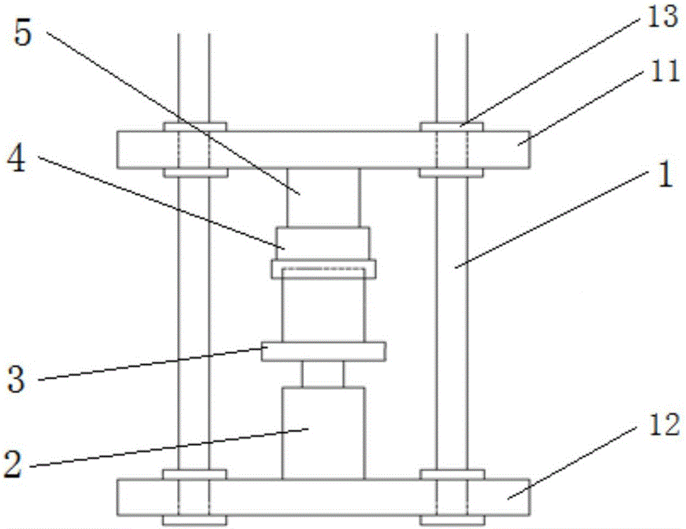
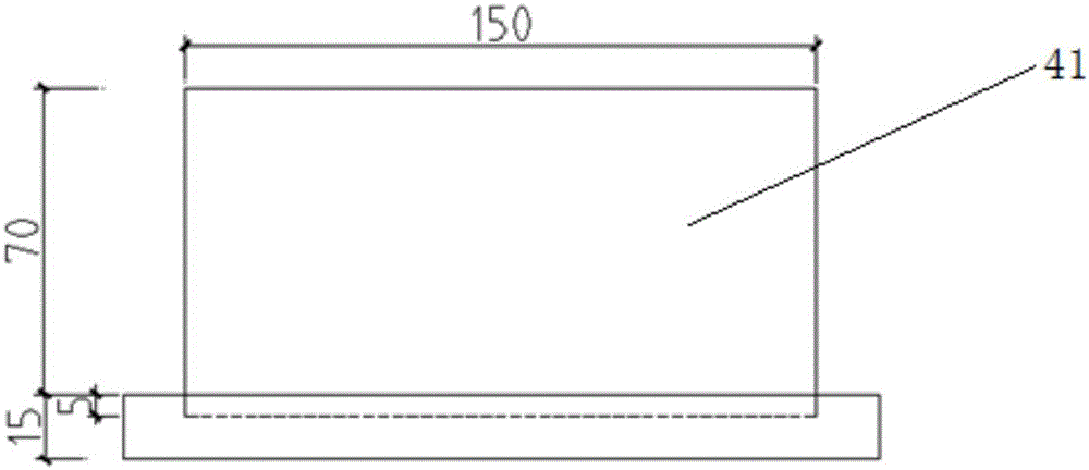
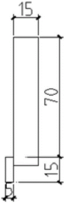
[0036] See figure 1 , taking a 150mm×150mm×150mm steel mold as an example, the pressing device for raw soil-based materials includes a test bench 1. The test bench 1 is provided with four columns perpendicular to the plane in four directions, and the test bench 1 is sequentially along the The first platform 11 and the second platform 12 are arranged side by side in the horizontal direction, and the four columns pass through the first platform 11 and the second platform 12 and are respectively fixed by anchor members 13. The anchor members 13 are screwed and fixed by bolt members. On the platform 12, a jack 2, a mold 3 and a pressure column 5 are coaxially arranged vertically from bottom to top in sequence, and the top of the pressure column 5 is tightly pressed against the first platform 11. A retaining hoop 4 is coaxially arranged between the mold 3 and the pressure column 5, the top end of the retaining hoop 4 is sleeved outside the pressure column 5, the bottom end of the r...
Embodiment 2
[0039] Embodiment 2: the contrast of sample preparation method
[0040] Taking a cubic steel mold of 150mm×150mm×150mm as an example, the compressive strength of cubic raw soil-based material specimens prepared by three different manufacturing methods: traditional hammering method, press compaction method and jack compaction method Experimental analysis, study the size and appearance of the test piece after forming, the density of the test piece after forming, and the compressive strength of the test piece after 28 days. Observe the test failure form, the location of cracks, study the stress distribution state, and carry out statistical analysis and stability analysis on the data. Study the commonality and difference of the three production methods, and find out the more suitable production method of the cube specimen of raw soil material.
[0041] Traditional hammering method:
[0042] Put the cubic steel mold flat on a solid ground, install the casing, apply a thin layer o...
PUM
| Property | Measurement | Unit |
|---|---|---|
| Thickness | aaaaa | aaaaa |
Abstract
Description
Claims
Application Information