
Tensile clamp for self-lubricating wedge jaw testing machine

A wedge-shaped pliers and testing machine technology, applied in the field of testing machines, can solve problems such as poor sliding, shortened life, change in the coaxiality of jaws, etc. The effect of the eccentricity of the mouth

Inactive Publication Date: 2016-08-24
济南天辰试验机制造有限公司
View PDF8 Cites 7 Cited by
  • Summary
  • Abstract
  • Description
  • Claims
  • Application Information

AI Technical Summary

Problems solved by technology

[0004] In the tensile fixture with the above structure, the inclined surface of the slider slides directly on the surface of the side wall of the U-shaped cavity of the clamping seat, and the sliding between the plane motion pair formed by the slider and the side wall of the U-shaped cavity produces strong extrusion friction. It is necessary to apply lubricating oil, because the positive pressure will increase with the progress of the movement. At this time, under such a high-intensity pressure, the lubricating oil film between the friction surfaces will be destroyed after only a few reciprocations, and even the lubricating oil will be consumed. As far as possible, the sliding between the slider and the side wall of the U-shaped cavity is not smooth, the friction coefficient increases, and the slider crawls. Therefore, it needs to be disassembled and relubricated repeatedly, and the maintenance frequency is high; with the increase in the number of uses , the friction coefficient will become larger and larger, and excessive friction will also cause the side wall surface of the U-shaped cavity of the clamping seat or the slider to wear quickly when the slider slides, and it is easy to be scratched, stuck, and the gap is too large. Reduced lifespan, troublesome repairs, and high maintenance costs
In addition, due to the large friction force and poor followability of the slider, the movement of the sliders on both sides is out of sync or crawling, which will inevitably cause changes in the coaxiality of the jaws, resulting in errors in the test results.
Sometimes there is even a situation where the fixture is stuck, which leads to fluctuations in the test curve, which affects the software's judgment on the yield point of the sample, resulting in inaccurate test data

Method used


Image

  • Tensile clamp for self-lubricating wedge jaw testing machine
  • Tensile clamp for self-lubricating wedge jaw testing machine
  • Tensile clamp for self-lubricating wedge jaw testing machine

Examples


Embodiment 1

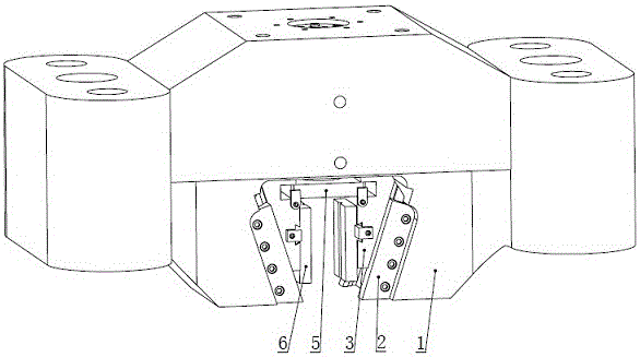
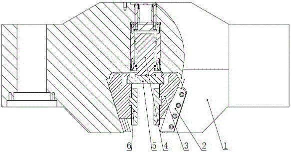
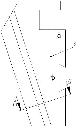
[0032] refer to Figure 1 to Figure 4 , a self-lubricating wedge-shaped jaw testing machine tensile fixture, including a clamping seat 1, a hydraulic cylinder 4, a jaw baffle 2, a slider 3, a power drive plate 5 and a clamping block 6, and the clamping seat 1 and the test The movable beam or the upper beam of the machine is an integrated structure. The clamping seat 1 has a U-shaped cavity with a narrow mouth and a wide bottom. The clamping block 6 is connected with one side of the slider 3. Jaws are formed between the blocks 6, and the other side of the slider 3 matches the side wall surface of the U-shaped cavity of the clamping seat 1 and forms a pair of sliding friction surfaces. The slider 3 can be formed in the U-shaped cavity. Slide in the space formed by the side wall surface and the jaw baffle plate 2; the piston rod of the hydraulic cylinder 4 passes through the bottom of the U-shaped cavity and is connected with the power drive plate 5; The matched sides of the sid...

Embodiment 2

[0034] refer to Figure 1 to Figure 4 , a self-lubricating wedge jaw testing machine tensile fixture, including a clamping seat 1, a hydraulic cylinder 4, a jaw baffle 2, a slider 3, a power drive plate 5 and a clamping block 6, and the slider 3 and The matching side of the side wall of the U-shaped cavity of the clamping seat 1 is coated with a wear-resistant material. The wear-resistant material in this embodiment is molybdenum disulfide. The slider is coated with molybdenum disulfide film by brushing, dipping or rolling. All the other structures are the same as in Embodiment 1.

Embodiment 3

[0036] refer to Figure 5 to Figure 8, a self-lubricating wedge-shaped jaw testing machine tensile fixture, including a clamping seat 1, a hydraulic cylinder 4, a jaw baffle 2, a slider 3, a power drive plate 5, and a clamping block 6, and the clamping seat 1 has a mouth It is a U-shaped cavity with a narrower part and a wider bottom. The clamping block 6 is connected to one side of the slider 3. A jaw is formed between the two clamping blocks 6. The other side of the slider 3 is connected to the clamping block. The side wall of the U-shaped cavity of the seat is corresponding; the piston rod of the hydraulic cylinder 4 passes through the bottom of the U-shaped cavity and is connected with the power drive plate 5; the slider 3 is connected to the side wall of the U-shaped cavity of the clamping seat The corresponding side is provided with a positioning groove, and the friction plate 10 is connected to the slider 3 by bolts, so that the friction plate 10 is embedded in the posi...


PUM


Abstract

The invention discloses a tensile clamp for a self-lubricating wedge jaw testing machine. A clamping base is provided with a U-shaped cavity with a narrow opening and a wider bottom. A clamping block is connected with one side face of a sliding block. The other side face of the sliding block corresponds to the side wall face of the U-shaped cavity of the clamping base. The side face, matched with the side wall face of the U-shaped cavity of the clamping base, of the sliding block is coated with a wear-resistant material or provided with a friction plate in an embedded mode, and a pair of sliding friction faces are formed. The friction faces do not need to be lubricated by an oil film, friction force between the sliding block and the clamping base can be lowered, the servo performance of the sliding block can be greatly improved, eccentricity of a jaw during a tensile test is overcome, a working face of the clamping base is protected forcefully, and scratches of the friction faces of the clamping base are eliminated; the phenomenon that a test curve fluctuates due to the fact the a clamp is clamped is avoided, the experimental data accuracy can be improved, the service life of the clamp can be prolonged, and the tensile clamp can work for a long time on the oil-free lubrication condition. After the clamp is used for a long time, only the friction plate needs to be replaced, and the sliding block or the clamping base does not need to be replaced.

Description

technical field [0001] The invention relates to a jig for a testing machine, in particular to a tensile jig for a wedge-shaped jaw testing machine, and belongs to the technical field of testing machines. Background technique [0002] In the tensile test of metal materials, most testing machines use wedge-shaped clamping jaws, which are generally composed of wedge-shaped clamping seats, hydraulic cylinders, jaw baffles, sliders, power drive plates, and clamping blocks. The structure is The left and right symmetrical forms, the clamping seat has a U-shaped cavity with a narrow mouth and a wide bottom. The clamping block is connected to the slider through a dovetail, and a jaw is formed between the two clamping blocks. The slider and the U-shaped There is a sliding friction surface between the side walls of the cavity, and the slider can slide in the space formed by the side walls of the U-shaped cavity and the jaw baffle; the piston rod of the hydraulic cylinder passes through...

Claims


Application Information

Patent Timeline
IPC IPC(8): G01N3/08G01N3/04
CPCG01N3/08G01N3/04
Inventor 王立刚冯国忠
Owner 济南天辰试验机制造有限公司
Learn More