Skew adjustable elevator counterweight device

A technology for elevators and counterweights, applied in the field of elevators, can solve problems such as increased energy consumption of elevators, increased friction between guide shoes and guide rails, and limited operating speed, so as to improve smooth running performance, improve friction conditions, and improve coordination the effect of the situation

Active Publication Date: 2015-12-09
SHUN DA BO NAI TE ELEVATOR
View PDF10 Cites 0 Cited by
  • Summary
  • Abstract
  • Description
  • Claims
  • Application Information

AI Technical Summary

Problems solved by technology

Due to the manufacturing deviation of the counterweight and other reasons, after the counterweight device is assembled, the verticality of the front and rear sides of the straight beam of the counterweight frame will have a certain deviation, and it is difficult to adjust
The deviation of the verticality of the front and rear sides of the straight beam of the counterweight frame will cause the side of the guide shoe to cooperate poorly with the side of the guide rail, which will increase the friction between the guide shoe and the guide rail, resulting in uneven wear of the guide shoe or guide rail. Increase the energy consumption of the elevator operation, which is not conducive to the smooth operation of the elevator
For large-tonnage elevators that can only use fixed sliding guide shoes, what is more serious is that it will cause the elevator to be stuck. However, at present, it can only be solved by improving the manufacturing and installation accuracy of guide rails and guide shoes, and The running speed is also greatly limited, which increases the difficulty of manufacturing, processing and installation of the elevator, and also affects the difficulty of elevator use and maintenance.

Method used


Image

  • Skew adjustable elevator counterweight device
  • Skew adjustable elevator counterweight device
  • Skew adjustable elevator counterweight device

Examples


Embodiment 1

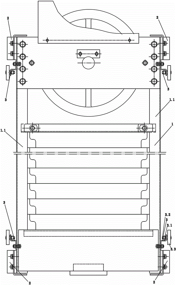
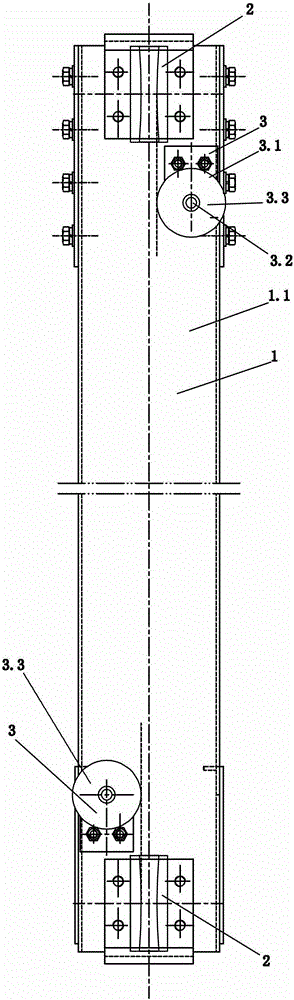
[0019] Such as figure 1 , figure 2 , image 3 , Figure 4 with Figure 5 As shown, it includes counterweight frame 1, guide shoe 2 and four deflection adjustment components 3. The counterweight frame 1 includes two left and right counterweight frame straight beams 1.1, and four guide shoes 2 are respectively arranged on the left side or the right side of one of the upper and lower ends of the left and right counterweight frame straight beams 1.1. The two deviation adjustment assemblies 3 are divided into two groups, and the two deviation adjustment assemblies 3 of one group are arranged symmetrically on the upper end of the counterweight frame and below the corresponding guide shoes 2, and the deviation adjustment assemblies 3 of the other group are symmetrically arranged on the left and right. It is located at the lower end of the counterweight frame and above the corresponding guide shoes; the upper and lower sets of deflection adjustment assemblies 3 are misaligned fro...

Embodiment 2

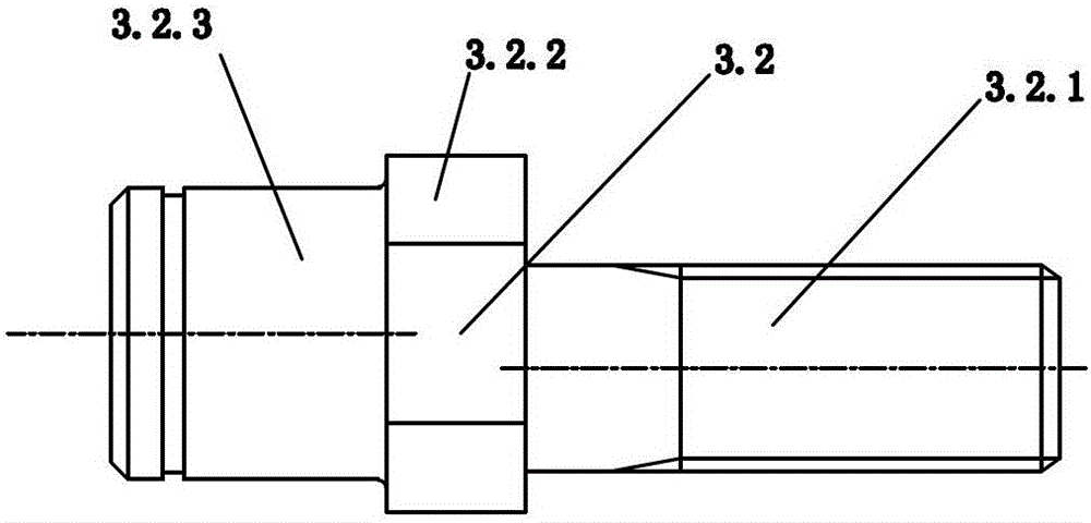
[0022] Such as Figure 6 As shown, the difference between the second embodiment and the first embodiment is that the bracket 3.1 of the deviation adjustment assembly 3 of the second embodiment is a cube-shaped part, which is fixed on the straight beam 1.1 with bolts, and is provided with a screw part 3.2. 1 Adapted screw holes, the screw part 3.2.1 is provided with fastening nuts and elastic washers, the free end of the screw part 3.2.1 is connected with the screw hole on the bracket 3.1, and the position of the eccentric shaft is adjusted with the screw part 3.2.1 The fastening nut set above is fixed at the adjusted position.

Embodiment 3

[0024] Such as Figure 7 , Figure 8 with Figure 9 As shown, the difference between the third embodiment and the first embodiment is that the bracket 3.1 of the deflection adjustment assembly 3 of the third embodiment is an L-shaped bracket. In the third embodiment, the support 3.1 of the upper group of deviation adjustment components 3 is connected to the front side of the upper beam of the counterweight frame with a bolt structure and the counterweight frame, and the support 3.1 of the lower group of deviation adjustment components 3 is connected with a bolt structure and a counterweight The frame is connected to the rear side of the lower beam of the counterweight frame, and the specific structural details of the connection are not repeated here because of the simple known technology.

[0025] The invention has simple structure and convenient use. The specific embodiments described above are only preferred implementation modes of the present invention, and are not inten...


PUM


Abstract

A deflected adjustable elevator counter-weight device comprises a counter-weight frame, guide shoes and a plurality of deflection adjusting components. The counter-weight frame comprises a left counter-weight frame straight girder and a right counter-weight frame straight girder, the four guide shoes are respectively arranged on the outer sides of the upper ends or the lower ends of the left counter-weight frame straight girder and the right counter-weight frame straight girder, the deflection adjusting components are divided into two groups, the deflection adjusting components in one group are bilaterally symmetrically arranged on the upper end of the counter-weight frame, the deflection adjusting components in the other group are bilaterally symmetrically arranged on the lower end of the counter-weight frame, and the deflection adjusting components in the two groups are staggered back and forth. Each deflection adjusting component comprises a support, an eccentric shaft and a deflection wheel, the eccentric shaft is formed by sequentially connecting a threaded screw portion, a wrench portion and a deflection adjusting wheel connecting portion, an axis of the screw portion is parallel to that of the deflection adjusting wheel connecting portion and vertical to left lateral sides or right lateral sides of the straight girders, one end of the support is fixedly connected with the counter-weight frame while the other end of the same is fixedly connected with the screw portion, and the deflection adjusting wheel is hinged with the deflection adjusting wheel connecting portion.

Description

technical field [0001] The invention relates to the field of elevators, in particular to an elevator counterweight device with adjustable deflection. Background technique [0002] The function of the weight balance system is to achieve a relative balance between the counterweight and the car, that is, to keep the weight difference between the car and the counterweight within a certain limit during the elevator operation, so as to balance the weight of the car and part of the elevator load weight , reduce the loss of motor power, and ensure that the traction drive of the elevator is stable and normal. The weight balance system consists of two parts: counterweight device and weight compensation device. The counterweight device generally includes a counterweight frame, a counterweight wheel, a counterweight buffer, a guide shoe, a counterweight and a counterweight pressure plate. The counterweight frame generally includes two straight beams, two upper beams and two lower beam...

Claims


Application Information

Patent Timeline
Patent Type & Authority Patents(China)
IPC IPC(8): B66B11/04B66B17/12
Inventor 潘辉周小炳全金刚
Owner SHUN DA BO NAI TE ELEVATOR
Why Eureka
Try Eureka