Energy-saving high-pressure and remote constant-pressure control axial variable plunger pump

A technology of constant pressure control and variable plunger, which is applied in the direction of variable displacement pump components, pumps, multi-cylinder pumps, etc., can solve the problem of increasing maintenance costs and maintenance difficulties, affecting the working efficiency and operation of plunger pumps, and plunger pumps. Reduce the service life of the pump and other problems, and achieve the effect of increasing the service life, improving the conveying efficiency, and reducing the energy consumption of conveying

Inactive Publication Date: 2019-04-05
四川省宜宾普什驱动有限责任公司
View PDF0 Cites 0 Cited by
  • Summary
  • Abstract
  • Description
  • Claims
  • Application Information

AI Technical Summary

Problems solved by technology

[0003] In the current plunger pump, since the sliding shoe adopts sliding friction during the contact process with the swash plate, the end face of the sliding shoe and the swash plate are greatly worn, which affects the working efficiency and operation of the plunger pump, causing the plunger The service life of the pump is greatly reduced, and the sliding shoes need to be replaced frequently to meet the needs of use, which increases the maintenance cost and difficulty of repair
However, in the prior art, most of the sliding shoes that can improve the friction between the sliding shoe and the swash plate have complex structures and high manufacturing costs.

Method used


Image

  • Energy-saving high-pressure and remote constant-pressure control axial variable plunger pump
  • Energy-saving high-pressure and remote constant-pressure control axial variable plunger pump
  • Energy-saving high-pressure and remote constant-pressure control axial variable plunger pump

Examples


Embodiment Construction

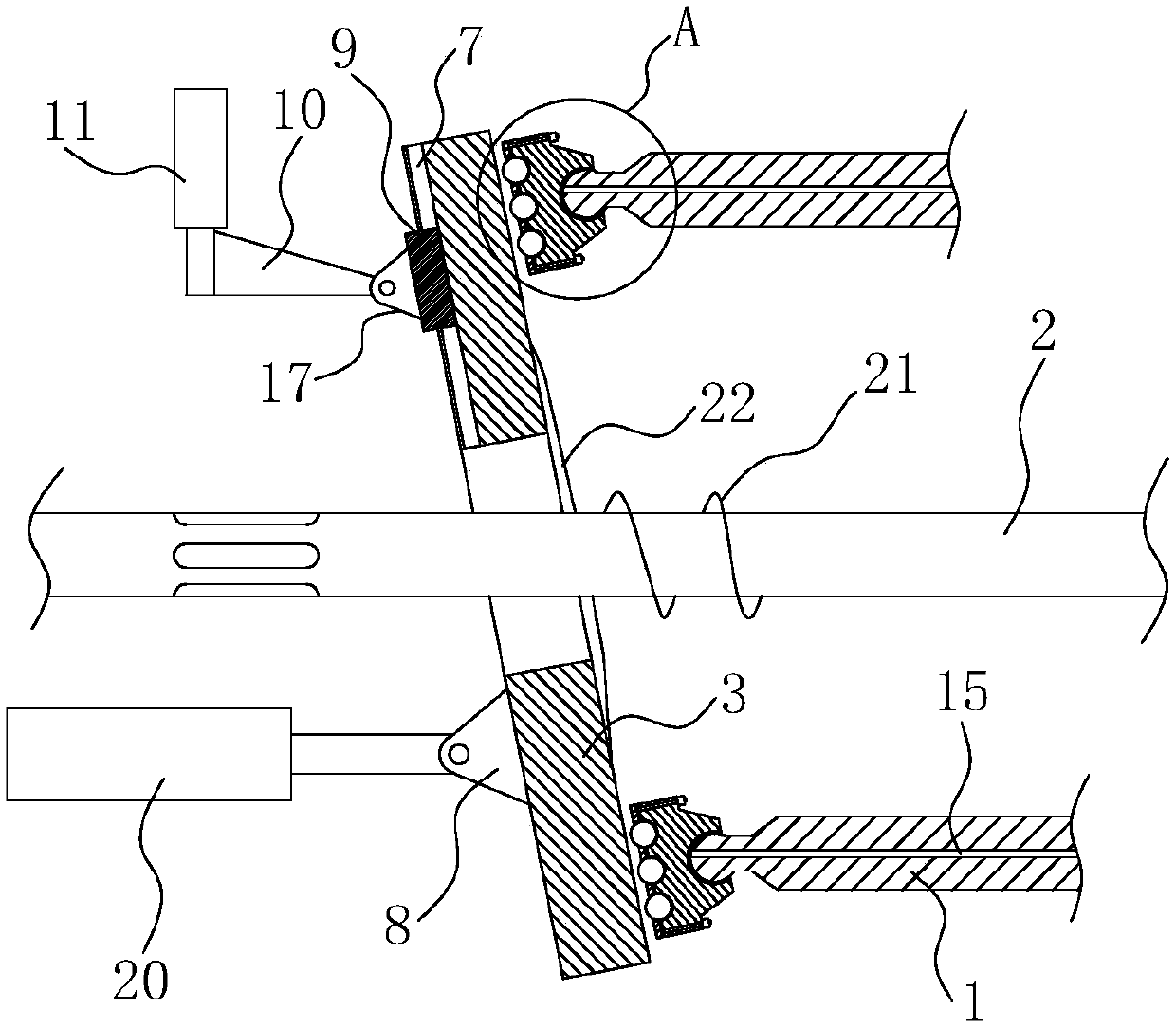
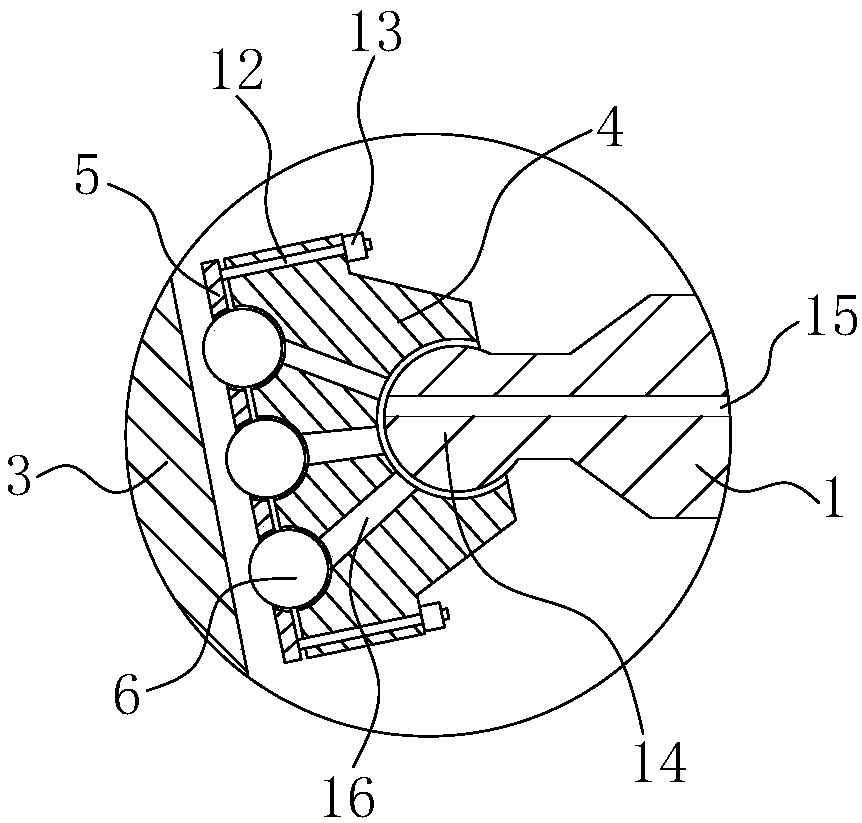
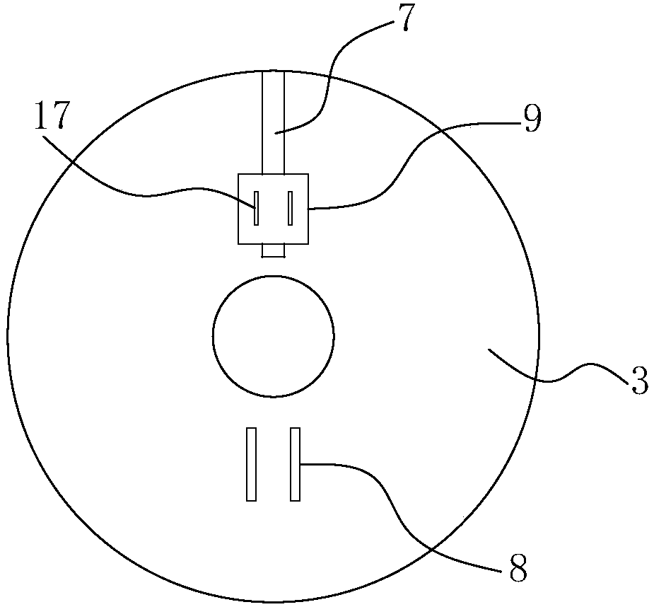
[0023] combine Figure 1-6 The shown is an energy-saving high-pressure, remote constant pressure control axial variable piston pump, including a plunger 1 and a swash plate 3 sleeved outside the transmission shaft 2; of course, the piston pump also includes a pump body, a cylinder body, a swash plate Seat, return plate, etc., due to the adoption of mature technology, there is no new improvement, so I will not repeat them here.

[0024] The transmission shaft 2 is located in the pump body, and a section of helical piece 21 is arranged on the shaft close to the swash plate 3. The swash plate 3 faces the disk surface of the plunger 1, and a deflector 22 is arranged outward along the center of the disk; The direction of rotation of the spiral piece 21 is the direction of direction in which the medium in the pump body is guided to the swash plate 3 . The extension direction of the guide vanes 21 is curved and facilitates the flow of the medium to the edge of the swash plate 3 . T...


PUM


Abstract

The invention relates to the technical field of pumps, and aims to provide an energy-saving high-pressure and remote constant-pressure control axial variable plunger pump. The friction condition between a swash plate and a sliding shoe can be effectively improved. According to the adopted technical scheme, the energy-saving high-pressure and remote constant-pressure control axial variable plungerpump comprises a plunger and the swash plate sleeving a transmission shaft; one end of the plunger is opposite to the swash plate and is provided with the sliding shoe; a segment of spiral sheet is arranged on a shaft body, located in a pump body and close to the swash plate, of the transmission shaft, and a flow guiding sheet is outwards arranged on the plate face, facing the plunger, of the swash plate along the center of the swash plate; and the rotating direction of the spiral sheet is the rotating direction that a medium in the pump body is guided to flow to the swash plate. According tothe energy-saving high-pressure and remote constant-pressure control axial variable plunger pump, heat generated when the sliding shoe makes friction with the swash plate is taken away advantageously;and heating and deformation of the swash plate and the siding shoe are lowered, the abrasion resisting performance of the sliding shoe is improved, and the service life of the sliding shoe is prolonged.

Description

technical field [0001] The invention relates to the technical field of pumps, in particular to an energy-saving, high-pressure, remote constant-pressure controlled axially variable plunger pump. Background technique [0002] Piston pumps are positive displacement pumps and reciprocating pumps. The plunger and the corresponding cylinder rotate in the pump body driven by the transmission shaft, and the swash plate surface is inclined relative to the transmission shaft, and is fixed and does not rotate in the pump body. During the rotation of the plunger, through contact with different positions of the swash plate, the stroke of the plunger in the cylinder is changed by the squeeze and pull of the swash plate, so as to realize the reciprocating motion of the plunger in the plunger cylinder; The pressure difference caused by the change of the sealed volume in the plunger cylinder can transport the fluid medium to work, and the flow rate of the plunger pump can be controlled by ...

Claims


Application Information

Patent Timeline
IPC IPC(8): F04B53/00F04B1/32F04B1/22F04B53/08F04B53/18
CPCF04B1/2078F04B1/2014F04B1/22F04B1/324F04B53/08F04B53/18
Inventor 王中伟雷德全冯晓磊刘猛杨莽
Owner 四川省宜宾普什驱动有限责任公司
Why Eureka
Try Eureka