
Terahertz scanning system and scanning method

A scanning system and scanning method technology, applied in instruments, measuring devices, scientific instruments, etc., can solve the problems of incident light intensity limitation, optical fiber transmission broadening, dispersion, etc., to enhance system stability, improve scanning speed, and reduce errors. Effect

Active Publication Date: 2018-10-23
UNIV OF SHANGHAI FOR SCI & TECH
View PDF5 Cites 0 Cited by
  • Summary
  • Abstract
  • Description
  • Claims
  • Application Information

AI Technical Summary

Problems solved by technology

However, due to the existence of optical fibers, the intensity of incident light is limited, and phenomena such as broadening, dispersion, and loss will occur during optical fiber transmission, which will bring unfavorable factors to the electric field scanning.

Method used


Image

  • Terahertz scanning system and scanning method
  • Terahertz scanning system and scanning method
  • Terahertz scanning system and scanning method

Examples


Embodiment 1

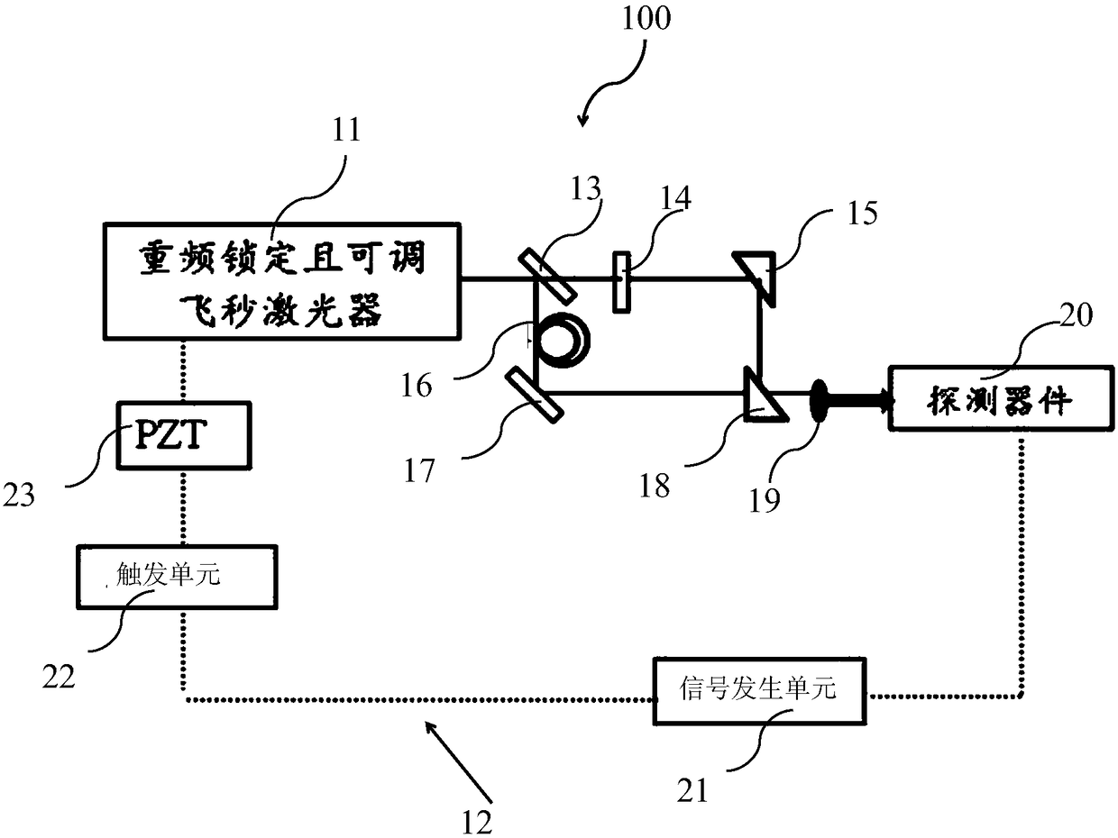
[0042] figure 1 It is a schematic structural diagram of the terahertz scanning system of this embodiment.

[0043] Such as figure 1As shown, the terahertz scanning system 100 includes a repetition-frequency-locked and tunable femtosecond laser 11, a repetition frequency tuning unit 12, a beam splitting unit 13, a terahertz pulse generating unit 14, a terahertz pulse collecting unit 15, and a pulse space offset generator Part 16, a reference laser pulse transmission direction changing part 17, a beam combining part 18, a focusing part 19, a photodetection part 20 and a processing part.

[0044] The repetition frequency locked and adjustable femtosecond laser is used to output a femtosecond laser with a pulse width of femtosecond level and lock the repetition frequency of the tuned femtosecond laser. The repetition frequency tuning part is used to tune the repetition frequency of the femtosecond laser, and includes a signal generation unit 21 , a trigger unit 22 and a tuning u...

Embodiment 2

[0067] In the second embodiment, the same structures as those in the first embodiment are assigned the same symbols and the same explanations are omitted.

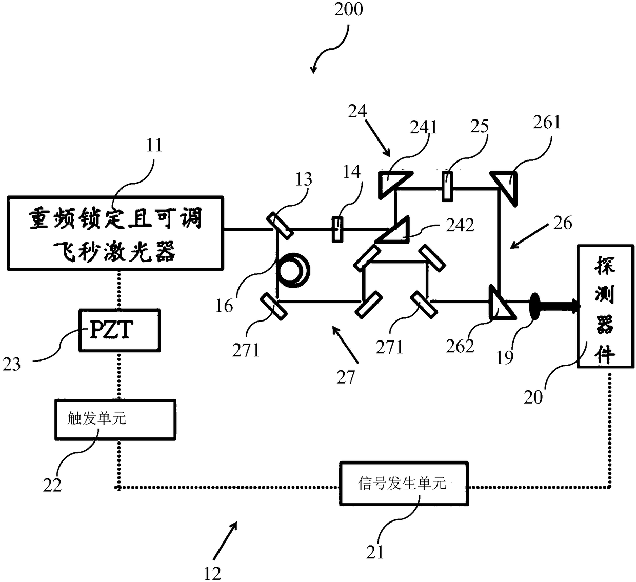
[0068] image 3 It is a schematic structural diagram of the terahertz imaging system in the second embodiment.

[0069] Such as image 3 As shown, the terahertz imaging system is used to identify the composition of the sample to be tested. Its structure is similar to that of the terahertz scanning system, including a repetition frequency locked and adjustable femtosecond laser 11, a repetition frequency tuning part 12, a beam splitting part 13, a Hertz pulse generation part 14, terahertz pulse collection part 24, sample storage part 25, pulse spatial offset generation part 16, reference laser pulse transmission direction changing part 27, beam combining part 26, focusing part 19, photodetection part 20 and processing.

[0070] The method for imaging the sample to be tested by using the terahertz imaging system includes ...


PUM


Abstract

The invention provides a terahertz scanning system and method. The scanning system comprises a repeat frequency locking and adjustable femtosecond laser device, a repeat frequency tuning part, a beam splitting part, a terahertz pulse generating part, a terahertz pulse collecting part, a pulse space shifting part, a reference laser pulse transmitting direction changing part, a beam combining part, a focusing part, a photoelectric detection part and a processing part. The repeat frequency tuning part comprises a signal generating unit, a triggering unit and a tuning unit, wherein the signal generating unit outputs an inherent-frequency electrical signal, the triggering unit uses the inherent-frequency electrical signal as a triggering signal and transmits the triggering signal to the femtosecond laser device, and the tuning unit continuously changes cavity length according to a feedback signal of the femtosecond laser device to tune repeat frequency. Then, the repeat frequency locking and adjustable femtosecond laser device locks the tuned repeat frequency.

Description

technical field [0001] The invention belongs to the field of terahertz scanning, and in particular relates to a terahertz scanning system and a scanning method. Background technique [0002] Terahertz is called the optical band of "non-destructive detection" due to its relatively weak photon energy. Since the rotational and vibrational energy levels of biomolecules (ie fingerprint spectrum) are mostly in the terahertz band, photons in this band can be used to analyze and manipulate the structure of biomolecules. Therefore, terahertz has important application value in biomedical imaging, detection and identification of material components. Overall, terahertz research in these areas is still in the laboratory stage, and large-scale applications still face many challenges. If the power of the existing terahertz radiation sources is low, the penetration of terahertz objects to be examined will be limited; the surrounding environment will interfere with terahertz radiation, suc...

Claims


Application Information

Patent Timeline
Patent Type & Authority Patents(China)
IPC IPC(8): G01N21/3586
CPCG01N21/3586G01N2201/10
Inventor 李敏郝强杨康文曾和平
Owner UNIV OF SHANGHAI FOR SCI & TECH
Learn More