Cutting-tool wear evaluation and prediction method and system based on generalized wear extent

A technology of tool wear and prediction method, applied in the field of metal cutting, can solve the problems such as the inability to fully characterize the tool wear pattern, the wear evolution process, the lack of measurement equipment, and the inability to meet the measurement requirements, and achieve the effect of optimizing the tool wear measurement research process.

Active Publication Date: 2016-08-24
ZHENGZHOU DIAMOND PRECISION MFG
View PDF4 Cites 11 Cited by
  • Summary
  • Abstract
  • Description
  • Claims
  • Application Information

AI Technical Summary

Problems solved by technology

Due to the lack of a complete and accurate system for expressing tool wear characteristics, and backward measuring equipment that cannot meet the measurement requirements, tool wear models and evaluation standards characterized by one-dimensional and two-dimensional representations are still widely used today.
With the development of workpiece materials and the development of corresponding tools, these two-dimensional static indicators, which are only measured from the appearance geometry, cannot fully characterize or even measure the wear pattern and wear evolution process of the tool.
For example, the same two-dimensional measurement results may represent different three-dimensional wear states; when describing tool wear under certain cutting parameters, it is easy to ignore the interaction and evolution mechanism of different states in the wear process

Method used


Image

  • Cutting-tool wear evaluation and prediction method and system based on generalized wear extent
  • Cutting-tool wear evaluation and prediction method and system based on generalized wear extent
  • Cutting-tool wear evaluation and prediction method and system based on generalized wear extent

Examples


example 3

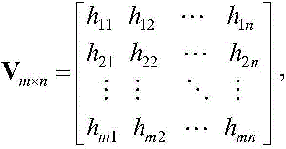
[0086] Example 3 Measurement of flank wear width

[0087] When there are only a few places (or one place) on the rake face (or flank face) that are severely worn and need to be focused on, the unequal step length measurement method can be used.

[0088] For example, each of the three areas of the flank C, B, and N has an obvious wear that needs to be measured, and the sampling length perpendicular to the cutting edge is l n , n is large enough, h Cj (1≤j≤n) is the height function of the jth sampling point near the cutting edge in the C area of ​​the cutter face, h Bj (1≤j≤n) is the height function of the jth sampling point close to the cutting edge in the region B of the cutter face, h Nj (1≤j≤n) is the height function of the jth sampling point close to the cutting edge in the area N of the knife face.

[0089] Then the generalized wear amount can be recorded as

[0090] V m × n = ...


PUM


Abstract

The invention discloses a cutting-tool wear evaluation and prediction method and system based on generalized wear extent. The method and the system can be used for supplementing shortages of the existing one-dimensional and two-dimensional measurement and evaluation methods and are beneficial to the optimization of a cutting-tool wear measurement and research process and the deep understanding of a cutting-tool wear pattern and an evolutionary process thereof, and thereby better instructing the design and use of cutting tools. The method comprises the following steps: (S1) acquiring wear state data of sampling points of a cutting tool in different sampling time periods, fitting the wear state data so as to obtain a state function of the sampling points of the cutting tool, and determining the generalized wear extent according to the state function; (S2) calculating cutting-tool wear evaluating indicators and a generalized wear rate based on the generalized wear extent; (S3) evaluating cutting-tool wear conditions according to the cutting-tool wear evaluating indicators, and predicting the cutting-tool wear conditions according to the generalized wear rate.

Description

technical field [0001] The invention relates to the technical field of metal cutting, in particular to a tool wear evaluation and prediction method and system based on generalized wear amount. Background technique [0002] Tool wear refers to the gradual loss of the original geometric angle of the tool due to physical or chemical effects during the normal cutting process. The wear, breakage and service life of the tool have a great influence on the processing quality, production efficiency and cost. Therefore, the measurement and evaluation of tool wear is of great significance to guide industrial production and improve processing quality and efficiency. Tool wear is a three-dimensional phenomenon. Due to the lack of a complete and accurate system for expressing tool wear characteristics, and backward measuring equipment that cannot meet the measurement requirements, tool wear models and evaluation standards characterized by one-dimensional and two-dimensional representati...

Claims


Application Information

Patent Timeline
Patent Type & Authority Applications(China)
IPC IPC(8): G06F19/00G06F17/15
CPCG06F17/15G16Z99/00
Inventor 孙剑飞杜大喜王凯陈五一
Owner ZHENGZHOU DIAMOND PRECISION MFG
Why Eureka
Try Eureka