
A Visual Transmission Electron Microscope Demonstration Device

A technology of electron microscope and demonstration device, which is applied in the direction of educational appliances, instruments, teaching models, etc., can solve the problems of high cost of use and maintenance, inability to thoroughly understand the principle of transmission electron microscope, difficulties, etc., and achieve easy universal use of components and clear principles , the effect of simple and clear structure

Active Publication Date: 2018-05-08
BEIJING INSTITUTE OF TECHNOLOGYGY
View PDF4 Cites 0 Cited by
  • Summary
  • Abstract
  • Description
  • Claims
  • Application Information

AI Technical Summary

Problems solved by technology

Moreover, the structure of the actual material sample is complex, and its images and diffraction patterns are relatively complicated, which is not helpful for beginners to understand the working principle of the transmission electron microscope;
[0006] (3) The purchase price of transmission electron microscope is expensive, the cost of use and maintenance is also high, and the quantity is small
It is difficult to meet the daily teaching work of universities and training institutions, and most students cannot operate it by themselves
[0007] The above three reasons, coupled with the fact that the theoretical basis of electron microanalysis is very abstract, lead to great difficulties for students in learning the principles of transmission electron microscopy, and they cannot thoroughly understand the principles of transmission electron microscopy. Manipulation technology becomes one of the most difficult scientific experiment technology courses to master

Method used

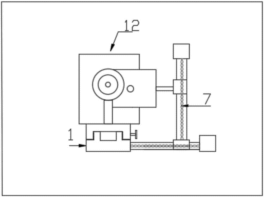
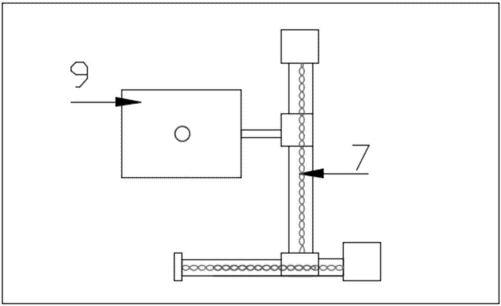

Image

  • A Visual Transmission Electron Microscope Demonstration Device
  • A Visual Transmission Electron Microscope Demonstration Device
  • A Visual Transmission Electron Microscope Demonstration Device

Examples


Embodiment 1

[0071] The focal length of the first lens is f1=130mm, the focal length of the second lens is f2=130mm, there is a scale on the base, the leftmost end is 0, the rightmost end is 1200mm, the collimated light source is located at 50mm, the sample grating is located at 155mm, the first The lens is located at 328mm, the aperture I is located at 458mm, the aperture II is located at 845mm, the second lens is located at 795mm, and the light screen is located at 895mm. The aperture I is inserted and the transmitted beam is selected. The image obtained at this time is as follows Figure 4 As shown, the mode at this time is the bright field image in the imaging mode.

Embodiment 2

[0073] The focal length of the first lens is f1=130mm, the focal length of the second lens is f2=130mm, there is a scale on the base, the leftmost end is 0, the rightmost end is 1200mm, the collimated light source is located at 50mm, the sample grating is located at 155mm, the first The lens is located at 328mm, the aperture I is located at 458mm, the aperture II is located at 845mm, the second lens is located at 795mm, and the light screen is located at 895mm. The aperture I is inserted and selects the diffracted beam in the horizontal direction, and the aperture II is not inserted. At this time The resulting image as Figure 5 shown. The mode at this time is the first dark field image in the imaging mode.

Embodiment 3

[0075] The focal length of the first lens is f1=130mm, the focal length of the second lens is f2=130mm, there is a scale on the base, the leftmost end is 0, the rightmost end is 1200mm, the collimated light source is located at 50mm, the sample grating is located at 155mm, the first The lens is located at 328mm, the aperture I is located at 458mm, the aperture II is located at 845mm, the second lens is located at 795mm, and the light screen is located at 895mm. The aperture I is inserted and selects the diffracted beam in the vertical direction, and the aperture II is not inserted. The image obtained when Figure 6 shown. The mode at this time is the second dark field image in the imaging mode.


PUM


Abstract

The invention relates to a visualization transmission electron microscope demonstration device, and belongs to the electron microscope demonstration technology field. By using laser to simulate a high energy electron beam of a transmission electron microscope, using a sample raster to simulate a crystal sample having a periodic structure, using a lens group plus a camera (or an optical screen) to simulate an imaging system of a transmission electron microscope, the simulation of the working mode of the transmission electron microscope is realized, and the characteristics such as clear and distinct principle, simple and clear structure, strong operability, universality of components, easy maintenance and replacement are provided, and the function is further expanded. The visualization transmission electron microscope demonstration device are capable of solving problems that teaching of a similar curriculum in a current phase is too abstract, because the main foundation of the curriculum is the book, and students cannot easily understand the relatively complicated working of the transmission electron microscope by adopting the teaching way suitable for the transmission electron microscope and the application method.

Description

technical field [0001] The invention relates to a visual transmission electron microscope demonstration device, which belongs to the technical field of electron microscope demonstration. Background technique [0002] Transmission electron microscope is a comprehensive analysis and testing instrument with ultra-high spatial resolution and various in-situ analysis functions. It is widely used in the field of material microstructure analysis. Therefore, at present, the materials colleges of major universities in China have set up materials analysis and testing technology courses, which specifically teach the principles and use of transmission electron microscopes. [0003] However, the following problems exist in the teaching of transmission electron microscopy: [0004] (1) The transmission electron microscope uses high-energy electron beams as the "light source". The electron beams are easily scattered by gas molecules and the trajectory changes, so it is required to work in...

Claims


Application Information

Patent Timeline
Patent Type & Authority Patents(China)
IPC IPC(8): G09B23/22
CPCG09B23/22
Inventor 岳峻逸谭成文苏铁健于晓东姜威宇
Owner BEIJING INSTITUTE OF TECHNOLOGYGY
Features
  • Generate Ideas
  • Intellectual Property
  • Life Sciences
  • Materials
  • Tech Scout
  • Unparalleled Data Quality
  • Higher Quality Content
  • 60% Fewer Hallucinations
Learn More