Clock synchronization method

A clock synchronization and clock technology, applied in the direction of electrical components, automatic power control, generation/distribution of signals, etc., can solve problems such as difficult timing design, achieve the effect of easy timing design and ensure delay time

Active Publication Date: 2016-08-24
MEGACHIPS
View PDF9 Cites 4 Cited by
  • Summary
  • Abstract
  • Description
  • Claims
  • Application Information

AI Technical Summary

Problems solved by technology

Since the clock path also changes in delay, it is difficult to design timing that satisfies the setup / hold constraints while considering the delay variation of the two paths.

Method used


Image

  • Clock synchronization method
  • Clock synchronization method
  • Clock synchronization method

Examples


Embodiment Construction

[0061] Hereinafter, the clock synchronization method of the present invention will be described in detail according to preferred embodiments shown in the accompanying drawings.

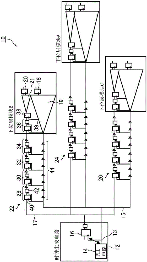
[0062] figure 1 It is a circuit diagram showing one embodiment of the structure of a semiconductor integrated circuit designed by applying the clock synchronization method of the present invention. The semiconductor integrated circuit 10 shown in this figure is a circuit designed by applying the clock synchronization method of the present invention and by a hierarchical layout design method, and has three lower layer modules A, B, C, and modules A, B, and C in addition to the lower layer modules. Top-level modules other than B and C.

[0063] The top module includes a clock generating circuit 12, the clock generating circuit 12 includes a PLL circuit 14 that generates a reference clock 15 with a constant cycle (frequency), and divides the reference clock 15 generated by the PLL circuit 14 by n (n is...


PUM


Abstract

The first synchronous FF is disposed at the starting point of the clock tree of the frequency-divided clock of each lower hierarchical block, and the first maximum delay time of the reference clock from the branch point of the reference clock and the frequency-divided clock to the first synchronous FF is acquired. The second maximum delay time of the reference clock between adjacent two of second synchronous FFs is determined so as to be less than half the period of the reference clock. The number of stages of the second synchronous FFs is determined according to the first and second maximum delay times. The target delay time from the branch point is determined so as to be not more than the second maximum delay time, and the second synchronous FF and a latch are disposed so as to achieve the target delay time.

Description

technical field [0001] The present invention relates to a clock synchronization method for synchronizing phases of a reference clock and a frequency-divided clock supplied from a clock generating circuit included in a top block to terminal FFs (flip-flops) included in a plurality of lower layer blocks. Background technique [0002] In the layout design of a large-scale semiconductor integrated circuit, a hierarchical layout design method is used. In the hierarchical layout design method, most circuits of a semiconductor integrated circuit are divided into a plurality of lower layer modules, and the layout design of each lower layer module is performed. Afterwards or at the same time, the layout design of the top modules other than the lower layer modules is performed, a clock signal is connected to each lower layer module, and wiring is connected between each lower layer module. [0003] In layout design of lower layer modules and top layer modules, a method called clock tr...

Claims


Application Information

Patent Timeline
Patent Type & Authority Applications(China)
IPC IPC(8): H03L7/10
CPCH03L7/10G06F1/10G06F1/04G06F1/08
Inventor 吉木保
Owner MEGACHIPS
Why Eureka
Try Eureka