Indoor floor positioning method based on TOA (Time Of Arrival)

A positioning method and floor technology, applied in the direction of electrical components, wireless communication, etc., can solve the problems that are not suitable for large-scale promotion and application, time-consuming, and high cost

Active Publication Date: 2016-08-24
NORTHWESTERN POLYTECHNICAL UNIV
View PDF4 Cites 12 Cited by
  • Summary
  • Abstract
  • Description
  • Claims
  • Application Information

AI Technical Summary

Problems solved by technology

Although this method can achieve a certain positioning accuracy, its preparatory work takes a long time, requires many positioning nodes (Access Point, AP) and high cost, and the positioning accuracy is cl

Method used


Image

  • Indoor floor positioning method based on TOA (Time Of Arrival)
  • Indoor floor positioning method based on TOA (Time Of Arrival)
  • Indoor floor positioning method based on TOA (Time Of Arrival)

Examples


Embodiment 1

[0077] In the first implementation example, the true height h where the MT to be located is located 0 =11.3m.

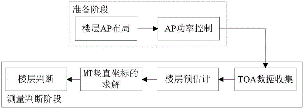
[0078] Step 1. The APs are laid out according to step 1, and the coordinates of the 4 APs are AP 1 (0, 0, 3.5), AP 2 (0.1, 0.2, 8.5), AP 3 (0.2, 0.1, 13.5), AP 4 (0.1, 0.1, 18.5), only consider the case where there is only one AP on each floor (the positioning method remains unchanged when multiple APs are arranged on each floor, and will not be discussed additionally) and the AP power control is as described in step 2;

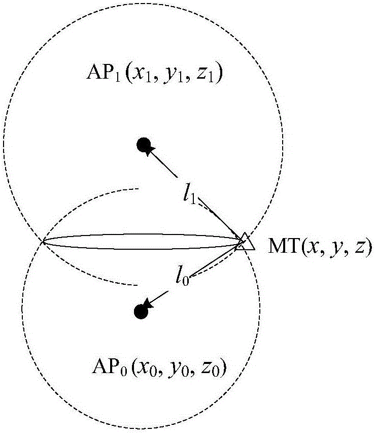
[0079] Step 2. After the MT is connected to the wireless network in the mall, it receives wireless signals from 3 APs, namely the AP 2 , AP 3 and AP 4 , these three APs can form two groups of positioning APs: APs 2 with AP 3 and AP 3 with AP 4 , among them, the group of APs with the highest signal strength is the AP 2 with AP 3 ;

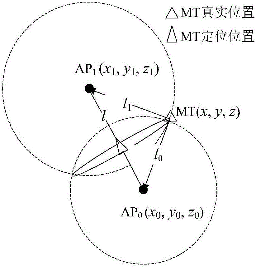
[0080] Step 3. Select with AP 2 with AP 3 Participate in positioning, and calculate the time t for the w...

Embodiment 2

[0086] In the second implementation example, the true height h where the MT to be located is located 0 =11.5m.

[0087] Step 1. The APs are laid out according to step 1, and the coordinates of the 4 APs are AP 1 (0, 0, 3.5), AP 2 (0.1, 0.4, 8.5), AP 3 (0.1, 0.2, 13.5), AP 4 (0.2, 0.2, 18.5), only consider the case where there is only one AP on each floor (the positioning method remains unchanged when multiple APs are arranged on each floor, and will not be discussed additionally) and the AP power control is as described in step 2;

[0088] Step 2. After the MT is connected to the wireless network in the mall, it receives wireless signals from 3 APs, namely the AP 2 , AP 3 and AP 4 , these three APs can form two groups of positioning APs: APs 2 with AP 3 and AP 3 with AP 4 , among them, the group of APs with the highest signal strength is the AP 2 with AP 3 ;

[0089] Step 3. Select with AP 2 with AP 3Participate in positioning, and calculate the time t for the w...

Embodiment 3

[0095] In the third implementation example, the true height h where the MT to be located is located 0 =10.8m.

[0096] Step 1. The APs are laid out according to step 1, and the coordinates of the 4 APs are AP 1 (0, 0, 3.5), AP 2 (0.2, 0.3, 8.5), AP 3 (0.1, 0.1, 13.5), AP 4 (0.1, 0.2, 18.5), only consider the case where there is only one AP on each floor (the positioning method remains unchanged when multiple APs are arranged on each floor, and will not be discussed additionally) and the AP power control is as described in step 2;

[0097] Step 2. After the MT is connected to the wireless network in the mall, it receives wireless signals from 3 APs, namely the AP 2 , AP 3 and AP 4 , these three APs can form two groups of positioning APs: APs 2 with AP 3 and AP 3 with AP 4 , among them, the group of APs with the highest signal strength is the AP 3 with AP 4 ;

[0098] Step 3. Select with AP 3 with AP 4 Participate in positioning, and calculate the time t for the w...


PUM


Abstract

The invention provides an indoor floor positioning method based on TOA (Time Of Arrival), and belongs to the field of positioning technology. The floor position of an MT (Mobile Terminal) to be solved can be pre-estimated according to the floor number of a positioning AP (Access Point) by controlling the transmitting power of the AP, and then the MT floor position solved by a specific algorithm is corrected to realize floor positioning of the MT to be solved, wherein a few positioning APs are adopted, so that the burden of the system is reduced, and the positioning cost is lowered; the positioning APs are arranged simply and quickly and are simple in positioning principle and high in positioning accuracy, so that the difference of transceiver gains does not need to be considered, the physical requirement for a transceiver antenna is reduced, the positioning complexity is low, a database does not need to be pre-established for a multi-floor building to be positioned, the positioning process is simplified, the portability is high, and the method can be combined with various different plane positioning methods to realize three-dimensional spatial positioning of a target to be positioned.

Description

technical field [0001] The invention belongs to the technical field of positioning, in particular to a positioning method for indoor floors. Background technique [0002] In modern life, people's daily work, leisure, entertainment, etc. are more and more concentrated in high-rise buildings. Therefore, the floors and the information they contain have gradually attracted people's attention. When users are in an indoor environment with complex building structures and densely populated areas such as commercial centers and stations, they often cannot quickly determine their own floor location. At this time, they hope to obtain relevant floor information through positioning applications. In recent years, the indoor plane positioning technology has become more and more mature, and various plane positioning systems have emerged one after another. However, in the actual positioning requirements, the indoor positioning technology of the two-dimensional plane often cannot meet the pos...

Claims


Application Information

Patent Timeline
IPC IPC(8): H04W64/00
CPCH04W64/00H04W64/006
Inventor 贺宏锟王晓飞许炎雷阳
Owner NORTHWESTERN POLYTECHNICAL UNIV
Why Eureka
Try Eureka