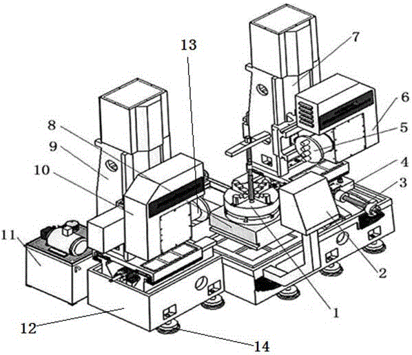
Machine tool for drilling operation of porous cylindrical workpiece and operation method

A cylindrical, machine tool technology, applied in the direction of boring/drilling, metal processing equipment, drilling/drilling equipment, etc., can solve the problems of low precision of drilling distribution, low drilling efficiency, low drum efficiency, etc. , to achieve the effect of improving indexing accuracy and indexing efficiency, high cost performance, automation degree and processing efficiency

Active Publication Date: 2016-08-31
德州德隆(集团)机床有限责任公司
View PDF6 Cites 3 Cited by
  • Summary
  • Abstract
  • Description
  • Claims
  • Application Information

AI Technical Summary

Problems solved by technology

[0004] This invention aims at the low efficiency of the current drilling equipment in batch processing cylindrical pressure rollers, cylindrical inner molds and drums, and solves the problems of low drilling efficiency and low precision of drilling distribution

Method used


Image

  • Machine tool for drilling operation of porous cylindrical workpiece and operation method

Examples


Embodiment Construction

[0027] Hereinafter, exemplary embodiments of the present disclosure will be described in more detail with reference to the accompanying drawings. Although exemplary embodiments of the present disclosure are shown in the drawings, it should be understood that the present disclosure can be implemented in various forms and should not be limited by the embodiments set forth herein. On the contrary, these embodiments are provided to enable a more thorough understanding of the present disclosure and to fully convey the scope of the present disclosure to those skilled in the art.

[0028] In the description of the invention, it should be understood that the terms "longitudinal", "lateral", "upper", "lower", "front", "rear", "left", "right", "vertical", " The orientation or positional relationship indicated by "horizontal", "top", "bottom", "inner", "outer", etc. are based on the orientation or positional relationship shown in the drawings, and are only for the convenience of describing ...


PUM


Abstract

The invention belongs to the technical field of drilling operation, and particularly relates to a machine tool for drilling operation of a porous cylindrical workpiece and an operation method of the machine tool. The machine tool comprises a machine tool base, a numerical control system, a numerical control rotary working table, a hydraulic system, drilling rod boxes, a four-jaw chuck, a left stand column and a right stand column; the drilling rod boxes comprise the left drilling rod box and the right drilling rod box; a left multi-shaft power head is arranged on the left drilling rod box, a right multi-shaft power head is arranged on the right drilling rod box, and the distance between the left multi-shaft power head and the right multi-shaft power head is adjustable; a rotating drag plate and a rotating lead screw are further arranged on one side of the machine tool base; and the machine tool has the beneficial effects that a machine tool structure for machining a cylindrical part is shaped to a eudipleural double three-coordinate structure, a left drilling rod box main shaft is provided with a multi-shaft drilling power head, and a right drilling rod box main shaft is provided with a multi-shaft drilling power head; the left side and the right side can carry out machining at the same time, and also can carry out independent machining; and high cost performance is achieved, the efficient semi-automatic machining manner can completely replace the original machining method for machining products of the same kind, and the automatic degree and the machining efficiency are greatly improved.

Description

technical field [0001] The patent of the invention belongs to the technical field of drilling, and in particular relates to a machine tool and an operation method for drilling a porous cylindrical workpiece. Background technique [0002] With the improvement of automated production capacity, there are more and more occasions in modern factories that require combined machine tools. Combined machine tools are semi-automatic or Automatic special machine tools. It generally adopts multi-axis, multi-tool, multi-process, multi-face or multi-station simultaneous processing methods, and its production efficiency is several to dozens of times higher than that of general-purpose machine tools. Since common components have been standardized and serialized, they can be flexibly configured according to needs, which can shorten the design and manufacturing cycle. Therefore, combined machine tools have the advantages of low cost and high efficiency, are widely used in mass production, an...

Claims


Application Information

Patent Timeline
Patent Type & Authority Applications(China)
IPC IPC(8): B23B39/22
CPCB23B39/22
Inventor 李敬伟张文强林晶伟曹振松刘铸
Owner 德州德隆(集团)机床有限责任公司
Why Eureka
Try Eureka