Vertical take-off and landing fixed-wing unmanned aerial vehicle

A vertical take-off and landing, fixed-wing technology, applied in the field of unmanned aerial vehicles, can solve the problems of difficult to control the balance of the body, high overall cost, large space occupied by the rotor, etc. Effect

Active Publication Date: 2016-08-31
BEIJING CASRS INFORMATION TECH
View PDF6 Cites 9 Cited by
  • Summary
  • Abstract
  • Description
  • Claims
  • Application Information

AI Technical Summary

Problems solved by technology

[0006] However, for UAVs, the structure is still too complicated, and in order to achieve practical stiffness, the requirements for structural accuracy and material rigidity are too high, the overall cost is high, and the balance of the body is difficult to control
[0007] In the prior art, there is also a scheme in which the rotor is embedded in the wing. In this scheme, a huge wing is provided on the body, and a through hole that penetrates up and down is provided on the wing. The rotor is arranged in the through hole. The rotor takes up a lot of space, the air fluid lift efficiency of the wing is not ideal, and the body is also relatively bulky

Method used


Image

  • Vertical take-off and landing fixed-wing unmanned aerial vehicle
  • Vertical take-off and landing fixed-wing unmanned aerial vehicle
  • Vertical take-off and landing fixed-wing unmanned aerial vehicle

Examples


Embodiment Construction

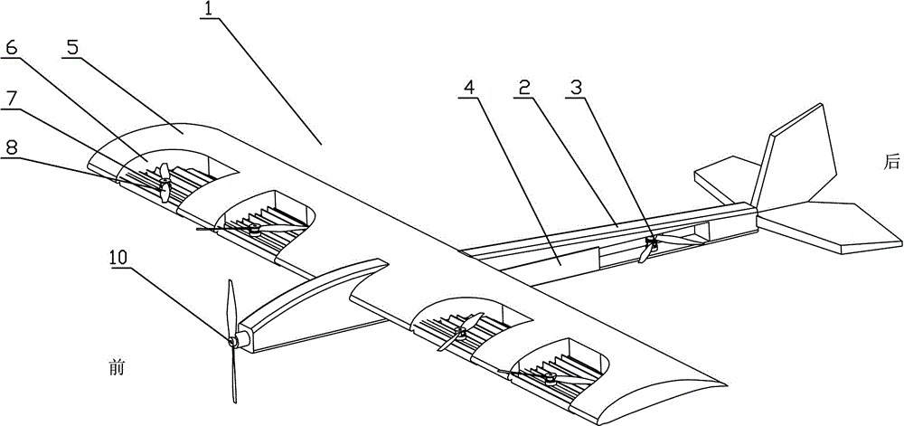
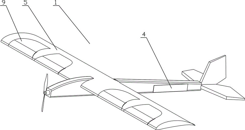
[0043] In the present invention, the orientation of the body 1 is used for illustration, that is, figure 1 For example, the head of the body 1 is the front, the tail is the rear, and the upper part of the body 1 is the top. The accompanying drawings in the present invention are all schematic diagrams. For the convenience of observation, some auxiliary structures are omitted, and only some structures related to the present invention are highlighted, which are some structures that are specially noted, and are commonly used structures in the prior art.

[0044] like figure 1 , 2Among them, a vertical take-off and landing fixed-wing UAV includes a fuselage 2, wings 5 ​​are provided on both sides of the fuselage 2, and a forward drive is provided on the fuselage 1. The forward drive described in this example, That is due to the device driving the whole body 1 to fly forward, including such as figure 1 The front rotor 10 shown in , or be located at the rotor below the wing or ahe...


PUM


Abstract

The invention provides a vertical take-off and landing fixed-wing unmanned aerial vehicle including a fuselage; wings are arranged at two sides of the fuselage; the fuselage is internally equipped with a foldable fuselage rotor wing; two sides of the fuselage rotor wing are equipped with fuselage slide plates; the wings are internally provided with a plurality of foldable wing rotor wings, and the top of each wing rotor wing is equipped with an openable-closable wing slide plate device. By adopting the structure, the unmanned aerial vehicle has the following beneficial effects that with adopting of forward driving and combination of the fuselage rotor wing and the wing rotor wings, switching between the vertical take-off and landing and fixed wing flight is convenient to realize. The unmanned aerial vehicle having the structure conveniently hovers at any time during task implementing, so that a camera can conveniently perform fixed-point observation, and at the same time, runways and ejection equipment are not required during take-off and landing. With the combination of the fuselage rotor wing and the wing rotor wings, the balance of the whole fuselage is convenient to control. With the use of the hidden type fuselage rotor wing and the hidden type wing rotor wings, no interference exists between the vertical take-off and landing mode and the fixed wing flight mode, and the size of the wings is not required to be increased. The lifting efficiency of air stream is high.

Description

technical field [0001] The invention relates to the field of unmanned aerial vehicles, in particular to a vertical take-off and landing fixed-wing unmanned aerial vehicle. Background technique [0002] Fixed-wing aircraft that take off and land vertically. This type of aircraft has similar functions to helicopters. It can take off and land vertically without using a runway. The difference is that this type of aircraft can accelerate from a hovering state to level flight through power tilting And transition to fixed-wing flight mode. For unmanned aerial vehicles, the fixed-wing solution of vertical take-off and landing can make the unmanned aerial vehicle land at the predetermined position. control advantage. [0003] At present, the practical vertical take-off and landing fixed-wing aircraft are mainly AV-8 Harrier fighter jet, V-22 Osprey tilt-rotor aircraft, and F-35 fighter jet. The AV-8 Harrier uses a Pegasus engine, and on the basis of a jet engine, it adopts a thrus...

Claims


Application Information

Patent Timeline
Patent Type & Authority Applications(China)
IPC IPC(8): B64C27/26B64C29/02
CPCB64C27/26B64C29/02
Inventor 魏俊彭斌
Owner BEIJING CASRS INFORMATION TECH
Why Eureka
Try Eureka