
A conveying device for industrial equipment

A technology for conveying devices and industrial equipment, which is applied in the field of conveying devices for industrial equipment, can solve problems such as the influence of the service life of the conveying device, expand the expenditure of economic costs, and reduce the service life of equipment, so as to avoid the difficulty of use and reduce the expenditure of economic costs , to prevent the effect of service life

Active Publication Date: 2018-05-01
嘉峪关澄宇金属材料有限责任公司
View PDF5 Cites 0 Cited by
  • Summary
  • Abstract
  • Description
  • Claims
  • Application Information

AI Technical Summary

Problems solved by technology

[0002] At present, the collected raw materials need to be further processed to achieve the effect of use. Both in transportation and processing, conveying devices are needed for better processing. However, the existing conveying devices generally use conveyor belts. The belt is driven by rolling rollers. During deep processing and manufacturing, industrial raw materials must stay and be processed during transportation, and the conveyor belt is used for transportation, so the motor needs to be shut down and started continuously, which is very inconvenient for users. The use of these products has caused great difficulties for users, increased working hours, increased the use of labor force, failed to meet the actual use requirements, expanded economic costs, affected the effect of use, and also affected The service life of the conveying device is affected, reducing the service life of the equipment

Method used


Image

  • A conveying device for industrial equipment
  • A conveying device for industrial equipment
  • A conveying device for industrial equipment

Examples


Embodiment Construction

[0015] The following will clearly and completely describe the technical solutions in the embodiments of the present invention with reference to the accompanying drawings in the embodiments of the present invention. Obviously, the described embodiments are only some, not all, embodiments of the present invention. Based on the embodiments of the present invention, all other embodiments obtained by persons of ordinary skill in the art without making creative efforts belong to the protection scope of the present invention.

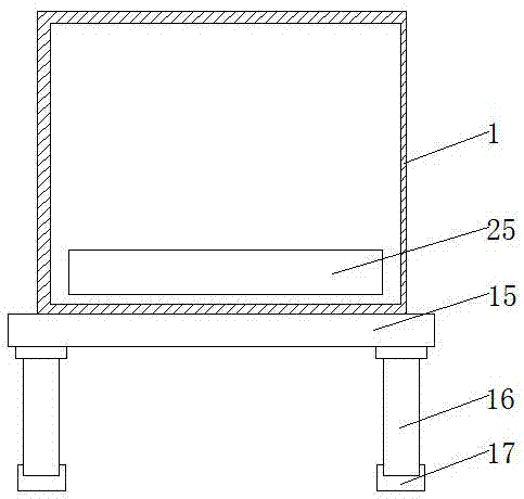
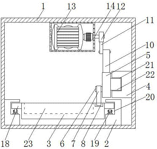
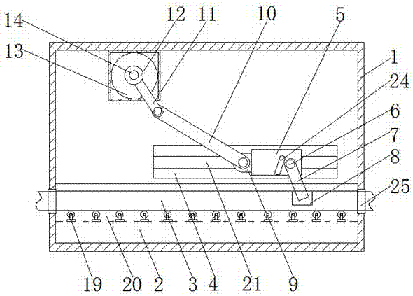
[0016] see Figure 1-3 , the present invention provides a technical solution: a conveying device for industrial equipment, including a casing 1, openings 25 are provided on both sides of the casing 1, the bottom of the casing 1 is fixedly connected with a bottom plate 15, and both sides of the bottom of the bottom plate 15 Both are fixedly connected with a column 16, and the bottom of the column 16 is fixedly connected with an anti-slip sleeve 17, and both sid...


PUM


Abstract

The invention discloses a conveying device for industrial equipment. The conveying device for the industrial equipment comprises an outer shell. Openings are formed in the front and rear sides of the outer shell correspondingly. The two sides of the bottom of the inner wall of the outer shell are fixedly connected with first fixed blocks correspondingly. A conveying plate is connected between the two first fixed blocks in a sliding mode. The two sides of the conveying plate both penetrate through the openings and extend to the outside of the openings. One side of the inner wall of the outer shell is fixedly connected with a second fixed block. The side, far away from the inner wall of the outer shell, of the second fixed block is connected with a movable block in a sliding mode. The side, far away from the second fixed block, of the movable block is fixedly connected with a fixing rod. By means of the conveying device for the industrial equipment, the problem that an industry conveying device in the present market can not meet the actual use requirements is solved, use is more convenient for a user, use difficulty caused to the user is avoided, the work time is shortened, use of labor force is lowered, economical cost output is reduced, and influences on the service life of the conveying device are prevented.

Description

technical field [0001] The invention relates to the technical field of industrial equipment, in particular to a conveying device for industrial equipment. Background technique [0002] At present, the collected raw materials need to be further processed to achieve the effect of use. Both in transportation and processing, conveying devices are needed for better processing. However, the existing conveying devices generally use conveyor belts. The belt is driven by rolling rollers. During deep processing and manufacturing, industrial raw materials must stay and be processed during transportation, and the conveyor belt is used for transportation, so the motor needs to be shut down and started continuously, which is very inconvenient for users. The use of these products has caused great difficulties for users, increased working hours, increased the use of labor force, failed to meet the actual use requirements, expanded economic costs, affected the effect of use, and also affecte...

Claims


Application Information

Patent Timeline
Patent Type & Authority Patents(China)
IPC IPC(8): B65G25/04
CPCB65G25/04
Inventor 张学舟闫肃李东荣赵新成胡俊
Owner 嘉峪关澄宇金属材料有限责任公司
Learn More