Disc transferring mechanism

A transmission mechanism and transmission motor technology, which is applied in the direction of conveyors, conveyor objects, rotary conveyors, etc., can solve the problems of materials falling to the ground, difficulty in meeting production use, and reducing the efficiency of disc transmission, so as to ensure efficiency and The effect of quality, simple structure

Inactive Publication Date: 2016-08-31
沈富强
View PDF7 Cites 3 Cited by
  • Summary
  • Abstract
  • Description
  • Claims
  • Application Information

AI Technical Summary

Problems solved by technology

[0002] At present, with the rapid development of industrial production, the transmission device is more and more widely used in the industry. In addition to horizontal linear transmission, the transmission device often needs to perform curved transmission. The disc transmission mechanism can be used as two transmission mechanisms. The transition between them can evenly transfer the material from one transmission mechanism to the other, so that the material can be conveyed in a curve, and it can also be used as a conveyor belt for flow operation between the two working platforms, avoiding regular material handling, thus To achieve continuous production, the existing disc transmission mechanism is generally fixed on the ground with bolts, which is difficult to move conveniently according to needs, and it is difficult to lift the transmission disc horizontally according to the needs of use during the use of the transmission disc. When the conveying disc conveys the material, the friction between the material and the conveying disc is often too small to cause the material to slip to the ground, which affects the normal transmission of the material, reduces the efficiency of the disc conveying, and is difficult to meet the production requirements. need

Method used


Image

  • Disc transferring mechanism

Examples


Embodiment Construction

[0011] In order to further describe the present invention, a specific implementation of a carousel transmission mechanism will be further described below in conjunction with the accompanying drawings. The following examples are for explanation of the present invention and the present invention is not limited to the following examples.

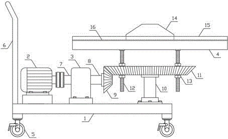
[0012] Such as figure 1 As shown, a disc transmission mechanism of the present invention includes a translation base 1, a transmission motor 2, a gearbox 3 and a transmission disc 4, a plurality of universal wheels 5 with brakes are evenly arranged on the lower side of the translation base 1, and the translation base 1 One side is provided with a push rod 6, the transmission motor 2 is horizontally arranged on one side above the translation base 1, the gearbox 3 is horizontally arranged on the translation base 1 on the side of the transmission motor 2, and the two sides of the gearbox 3 are respectively horizontally rotated and connected with in...


PUM


Abstract

The invention discloses a disc transferring mechanism, and belongs to the field of transferring mechanical equipment. The mechanism comprises a horizontal moving base, a transferring motor, a transmission and a transferring disc; a plurality of belt brake universal wheels are evenly arranged on the lower side of the horizontal moving base, a vehicle pushing rod is arranged on one side of the horizontal moving base, and an input shaft and an output shaft are horizontally and rotatably connected to the two sides of the transmission correspondingly; the output end of the transferring motor is in transmission connection with one end of the input shaft of the transmission, a master bevel gear is vertically arranged at one end of the output shaft of the transmission, and an auxiliary bevel gear disc is horizontally arranged at the upper end of a rotating shaft; the master bevel gear and the auxiliary bevel gear disc are in engaged connection; the transferring disc is horizontally arranged on the upper side of the auxiliary bevel gear disc, and a plurality of adjusting lead screws are vertically and evenly arranged between the transferring disc and the auxiliary bevel gear disc; and the mechanism is simple in structure, the disc transferring mechanism can be conveniently and rapidly moved horizontally, materials can be rapidly and efficiently transferred according to needs, and production and use needs are met.

Description

technical field [0001] The invention relates to a transmission mechanism, in particular to a disc transmission mechanism, which belongs to the field of transmission mechanical equipment. Background technique [0002] At present, with the rapid development of industrial production, the transmission device is more and more widely used in the industry. In addition to horizontal linear transmission, the transmission device often needs to perform curved transmission. The disc transmission mechanism can be used as two transmission mechanisms The transition between them can evenly transfer the material from one conveying mechanism to another conveying mechanism, so that the material can be conveyed in a curve, and it can also be used as a conveyor belt for flow operation between two working platforms, avoiding regular material handling, thus To achieve continuous production, the existing disc transmission mechanism is generally fixed on the ground with bolts, which is difficult to ...

Claims


Application Information

Patent Timeline
Patent Type & Authority Applications(China)
IPC IPC(8): B65G29/00B65G41/00
CPCB65G29/00B65G41/008Y02P70/10
Inventor 沈富强
Owner 沈富强
Why Eureka
Try Eureka