Dustproof structure of sewing machine housing
A dust-proof structure, sewing machine technology, applied in the field of sewing machines, can solve the problems of encoder, grating influence, dust, and sewing work cannot be carried out in an orderly manner, and achieves the effect of good dust-proof effect, prolonging service life and small gap.
- Summary
- Abstract
- Description
- Claims
- Application Information
AI Technical Summary
Problems solved by technology
Method used
Image
Examples
Embodiment 1
[0029] The dust-proof structure refers to a filter screen arranged on the hand wheel 4 to prevent dust from entering the protective cover 2 . The filter screen is arranged on the inner wall or the outer wall of the hand wheel 4 to directly block the dust, and the wind can still enter the protective cover 2 through the filter screen. This structure is simple and convenient, but the filter screen needs to be cleaned frequently.
Embodiment 2
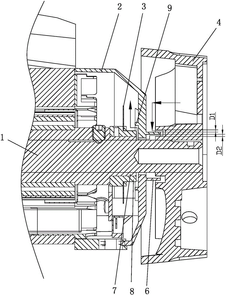
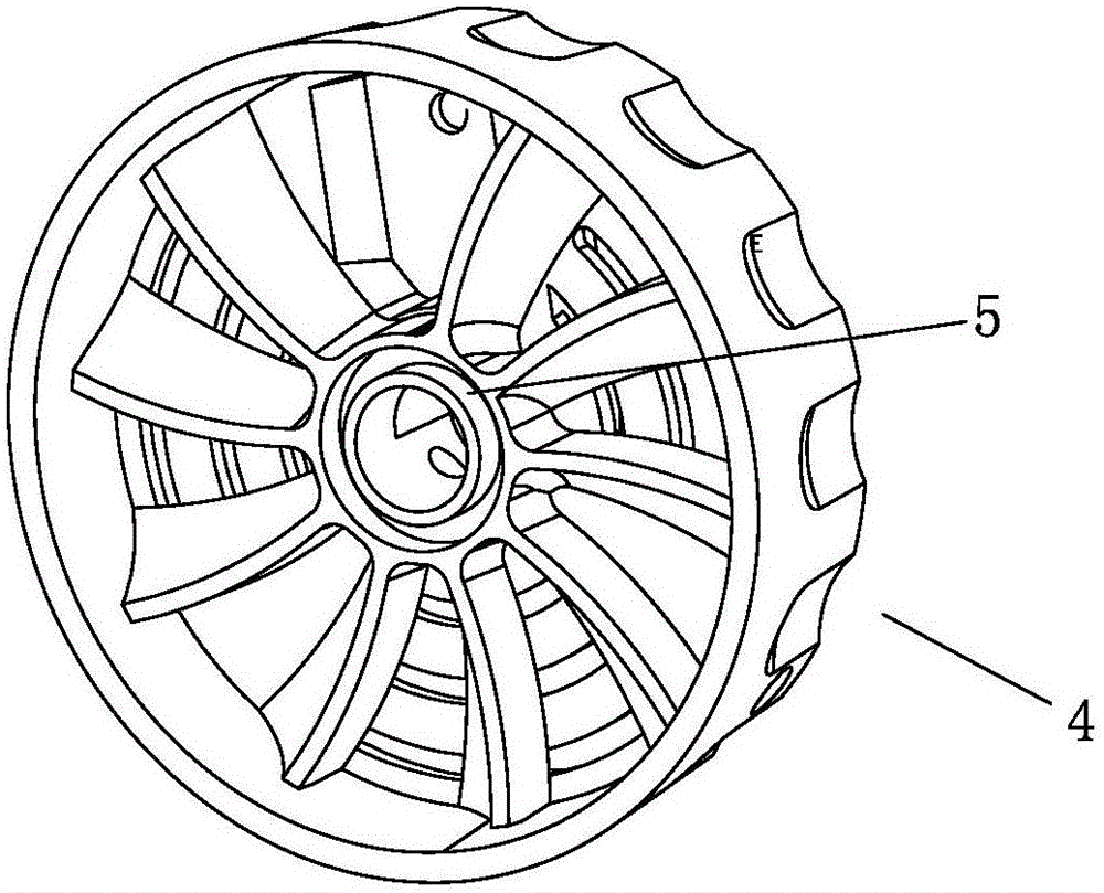
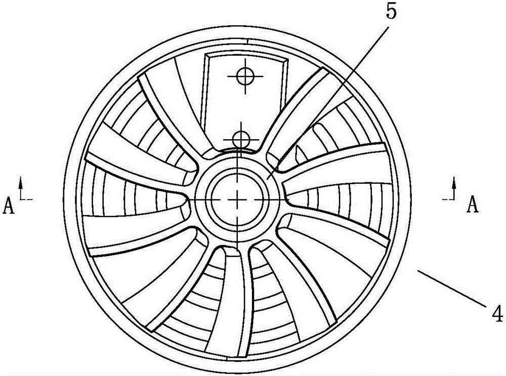
[0031] The dust-proof structure can also be a small multi-bending air inlet air duct formed between the hand wheel 4 , the protective cover 2 and the main shaft 1 . like figure 1 , 2 , 3, 4 shown.
[0032] The multi-bending air inlet duct is as follows: an annular groove 5 is provided on the inner surface of the hand wheel 4, and an annular protrusion 6 extends outward along the axial direction of the main shaft 1 on the corresponding outer surface of the protective cover 2. One end of the protrusion 6 is inserted in the annular groove 5, a gap is formed between the annular protrusion 6 and the annular groove 5, and between the outer side wall of the annular groove 5 and the outer cylindrical surface of the annular protrusion 6, Between the end surface of the annular protrusion 6 and the inner bottom of the annular groove 5, between the inner wall of the annular groove 5 and the inner cylindrical surface of the annular protrusion 6, between the inner cylindrical surface of t...
Embodiment 3
[0036] This embodiment and the second embodiment adopt different multi-bending air inlet ducts: on the outer surface of the protective cover 2, there is an annular protrusion 6 extending axially outward along the main shaft 1, and the outer end of the annular protrusion 6 is close to the handwheel 4, and form a gap between the outer end surface of the annular protrusion 6 and the inner side wall of the hand wheel 4, between the outer end surface of the annular protrusion 6 and the inner side wall of the hand wheel 4, the inner side wall of the annular protrusion 6 Between the inner cylindrical surface and the main shaft, and between the inner hole wall of the protective cover 2 and the main shaft 1, a multi-bending air inlet air duct is formed. like Figure 5 shown.
[0037] Wherein, the distance D3 between the outer end surface of the annular protrusion 6 and the inner side wall of the hand wheel 4 is 1±0.05mm, generally 1mm is selected, which can effectively prevent dust wi...
PUM
 Abstract
Description
Claims
Application Information
 - R&D
- Intellectual Property
- Life Sciences
- Materials
- Tech Scout
- Unparalleled Data Quality
- Higher Quality Content
- 60% Fewer Hallucinations
Browse by: Latest US Patents, China's latest patents, Technical Efficacy Thesaurus, Application Domain, Technology Topic, Popular Technical Reports.
© 2025 PatSnap. All rights reserved.Legal|Privacy policy|Modern Slavery Act Transparency Statement|Sitemap|About US| Contact US: help@patsnap.com


