
An assembled rotary compensator for pipelines

A rotary compensator and cartridge-type technology, which is applied to expansion compensation devices for pipelines, pipe elements, pipes/pipe joints/fittings, etc., can solve the problem of low packing utilization of seals, and achieve reasonable setting, Good sealing effect and high sealing reliability

Active Publication Date: 2018-02-13
JINAGSU SUNPOWER PIPELINE ENG TECH CO LTD
View PDF11 Cites 0 Cited by
  • Summary
  • Abstract
  • Description
  • Claims
  • Application Information

AI Technical Summary

Problems solved by technology

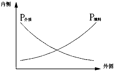
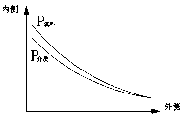
[0003] The purpose of the present invention is to design a method that can make the seal compress the seal in order to solve the problem that the compression force variation trend of the end face seal of the existing rotary compensator is opposite to the change of the medium pressure, which leads to the low utilization rate of the packing as the seal. Manifold Rotary Compensator for Pipeline with Force Variation Trend Consistent with Medium Pressure Variation

Method used


Image

  • An assembled rotary compensator for pipelines
  • An assembled rotary compensator for pipelines
  • An assembled rotary compensator for pipelines

Examples


Embodiment Construction

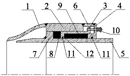
[0018] The present invention will be further described below in conjunction with the accompanying drawings and embodiments.

[0019] Such as figure 1 shown.

[0020] An assembly-type rotary compensator for pipelines, which includes a reducing tube 1, a sealing seat 2, a gland 4 and a core tube 5, and one end of the core tube 5 provided with an annular outer boss 7 extends into the reducing tube 1 , the reducing tube 1, the sealing seat 2 and the gland 4 are connected in pairs and are integrally set on the core tube 5, wherein the gland 4 is connected to the sealing seat 2 through the connecting plate 6 by welding. In the cavity formed by the sealing seat 2, the gland 4 and the core tube 5, a sealing chamber sleeve 3 is provided, and one end of the sealing chamber sleeve 3 is provided with an annular inner boss 12, and the other end is connected to the gland 4 through a fastener 10; A first sealing cavity is formed between the annular outer boss 7, the sealing cavity cover 3...


PUM


Abstract

The invention discloses a combined rotary compensator for pipelines. The combined rotary compensator comprises a reducer pipe, a sealing base, a sealing cavity sleeve, a gland and a core pipe; the end with an annular outer boss of the core pipe extends into the reducer pipe; every two of the reducer pipe, the sealing base and the gland are connected, and the reducer pipe, the sealing base and the gland are installed on the core pipe in a sleeving mode as a whole; the sealing cavity sleeve is arranged in a cavity formed by the sealing base, the gland and the core pipe, an annular inner boss is arranged at one end of the sealing cavity sleeve, and the other end of the sealing cavity sleeve is connected to the gland through a fastener; the annular outer boss, the sealing cavity sleeve and the sealing base form a first sealing cavity, and an end face sealing element is installed inside the first sealing cavity; the sealing cavity sleeve, the gland and the core pipe form a second sealing cavity, and a ring surface sealing element is installed inside the second sealing cavity. The combined rotary compensator increases the utilization rate of filler and is longer in service life and higher in sealing reliability.

Description

technical field [0001] The invention relates to a pipeline compensation technology, in particular to a rotary compensator, in particular to a packaged rotary compensator for pipelines. Background technique [0002] At present, as a new type of compensation device for pipeline thermal expansion, the rotary compensator has the advantages of large compensation amount, convenient installation, and low overall cost, and has been widely used in the fields of electric power, petrochemical, and heating. The typical rotary compensator structure is shown in Chinese patent ZL200610041301.4. Through the force analysis of the rotary compensator, it is found that the existing structure design is unreasonable. Low, especially the packing on the side away from the gland can't play a sealing effect at all. Contents of the invention [0003] The purpose of the present invention is to design a method that can make the seal compress the seal in order to solve the problem that the compression...

Claims


Application Information

Patent Timeline
Patent Type & Authority Patents(China)
IPC IPC(8): F16L51/00
CPCF16L51/00
Inventor 郭宏新沈建锋刘丰李炎吴然
Owner JINAGSU SUNPOWER PIPELINE ENG TECH CO LTD
Learn More