
Rotary drying device and drying technology

A technology of rotary drying and equipment, which is applied in the direction of drying solid materials, drying gas arrangement, lighting and heating equipment, etc. It can solve the problems of high air leakage rate, corrosion and sealing difficulties, and achieve the effect of saving energy and improving thermal efficiency

Active Publication Date: 2016-08-31
HUNAN DINGJIU ENERGY & ENVIRONMENT TECH LTD
View PDF15 Cites 9 Cited by
  • Summary
  • Abstract
  • Description
  • Claims
  • Application Information

AI Technical Summary

Problems solved by technology

However, the structure of the drying rotary kiln is complicated, and the drying medium pipeline placed inside the drum is easily corroded by the material, the failure rate is high, and it is not easy to maintain
In addition, due to the continuous rotation of the drum of the existing rotary drying furnace, the sealing surfaces between the two ends of the drum and the furnace head and the furnace tail are relatively large. Therefore, it is difficult to seal the drum and the furnace head and furnace tail, and the air leakage rate is high, especially high Due to the thermal expansion and contraction of the furnace body and the limitation of high-temperature dynamic sealing materials, the sealing effect of the rotary furnace under the working temperature is very poor, which has a great impact on the production process; in addition, because the drying process consumes a lot of heat energy, the existing rotary drying Due to the limitation of the rotating structure of the drum, the equipment cannot make full use of the heat in the drying process
[0004] In summary, how to solve the problems of complex structure, high failure rate and inconvenient maintenance of the existing rotary drying furnace has become an urgent problem to be solved by those skilled in the art

Method used


Image

  • Rotary drying device and drying technology
  • Rotary drying device and drying technology
  • Rotary drying device and drying technology

Examples


Embodiment Construction

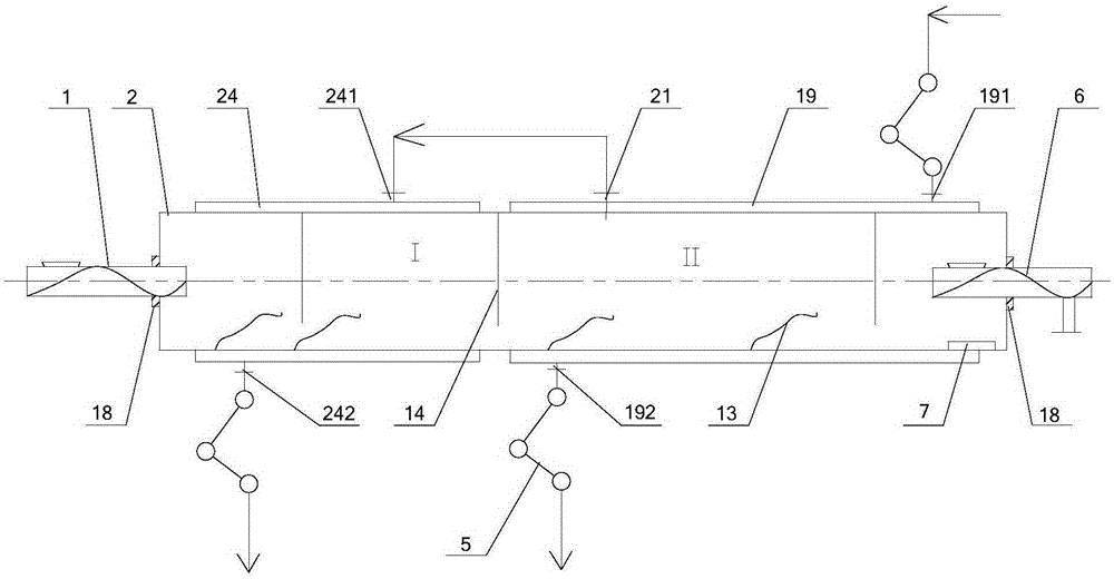
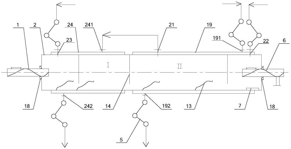
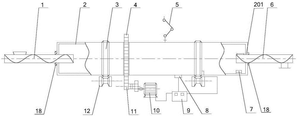
[0059] The core of the present invention is to provide a rotary drying equipment, which simplifies the structure of the equipment, reduces the failure rate and is convenient for maintenance.

[0060] The invention also provides a drying process, which can use the heat of the steam generated by the drying to preheat the material and improve the heat utilization rate.

[0061] The technical solutions in the embodiments of the present invention will be clearly and completely described below in conjunction with the accompanying drawings in the embodiments of the present invention. Obviously, the described embodiments are only a part of the embodiments of the present invention, rather than all the embodiments. Based on the embodiments of the present invention, all other embodiments obtained by those of ordinary skill in the art without creative work shall fall within the protection scope of the present invention.

[0062] Please refer to Figure 1-Figure 3 with Picture 9 with Figure 14 ...


PUM


Abstract

The invention discloses a rotary drying device, comprising a swing-type rotary furnace. The swing-type rotary furnace comprises a rotary drum, a driving device and a supporting device, a control device, and a heating jacket and / or dry hot gas inlet and outlet. The rotary drum is internally provided with a drying section. The cylinder wall of the vapor phase region of the drying section is provided with a steam outlet. The driving device and the supporting device are arranged out of the rotary drum, and are used to drive and support the rotary drum to swing back and forth around a rotating axis. The control device is connected with the driving device through a wire, and is used to control operation of the driving device. The heating jacket is arranged on the cylinder wall of the drying section. The heating jacket is provided with a hot medium inlet and a hot medium outlet which are connected with an external pipe through a moveable conduit assembly. Since the rotary drying device uses the swing-type rotary furnace, the rotary drum just swings back and forth in certain radian, and the cylinder wall of the rotary drum is provided with the heating jacket and the dry hot gas inlet and outlet. Compared with an existing built-in drying structure, the device is simple in structure, reduced in failure rate, and convenient in maintenance. The invention also discloses a drying technology.

Description

Technical field [0001] The invention relates to the technical field of chemical equipment, in particular to a rotary drying equipment. It also relates to a drying process. Background technique [0002] The drying of wet materials often uses indirect heating, that is, the heating medium does not directly contact the materials. Some dry products may contain dust, so the sealing performance of the drying equipment will be higher. [0003] The existing drying equipment is usually a rotary drying furnace. The rotary drying furnace is composed of a drum, a furnace head and a furnace tail. The furnace head and the furnace tail are fixedly rotating around the two ends of the drum and are connected to the two ends of the drum. Dynamic and static sealing, the drum is continuously rotated by an external drive device. Due to the continuous rotation of the drum of the existing rotary drying furnace, in order to achieve drying of the material, it is usually necessary to set up a complicated d...

Claims


Application Information

Patent Timeline
IPC IPC(8): F26B17/34F26B23/10F26B21/00F26B25/00F26B3/20F26B3/06
Inventor 姜良政
Owner HUNAN DINGJIU ENERGY & ENVIRONMENT TECH LTD
Learn More