Backlight modules and liquid crystal display equipment

A technology of backlight module and liquid crystal panel, applied in optics, nonlinear optics, instruments, etc.

Active Publication Date: 2019-09-20
HISENSE VISUAL TECH CO LTD
View PDF11 Cites 0 Cited by
  • Summary
  • Abstract
  • Description
  • Claims
  • Application Information

AI Technical Summary

Problems solved by technology

However, since the backlight module needs to be equipped with multi-layer optical films, including a variety of film combinations such as brightness enhancement film and diffusion film, among them, the surface of the brightness enhancement film is provided with microstructures arranged horizontally, which will form light rays on the plastic frame. The dark area is stretched in the horizontal direction, and the dark area after passing through the optical film will still expand to the visible area. Therefore, the dark area on the visible area forms a display shadow problem

Method used


Image

  • Backlight modules and liquid crystal display equipment
  • Backlight modules and liquid crystal display equipment
  • Backlight modules and liquid crystal display equipment

Examples


Embodiment 1

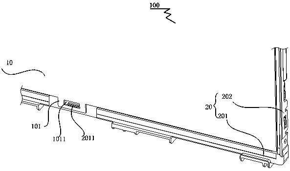
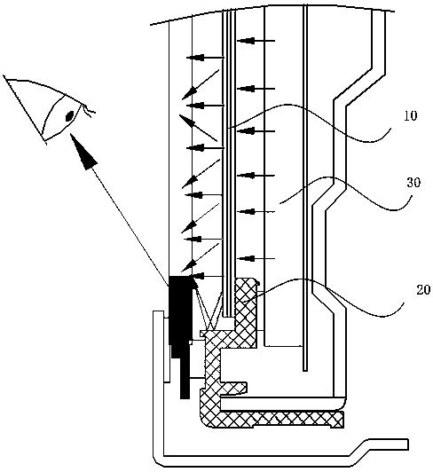
[0032] image 3 It is a schematic diagram of fixing the diaphragm of the backlight module in Embodiment 1 of the present invention; Figure 4 a is a schematic diagram of the A-A cross-section of the backlight module in Embodiment 1 of the present invention; Figure 5 It is a schematic diagram of the C-C section of the backlight module in Embodiment 1 of the present invention; Figure 6 It is a B-B cross-sectional schematic view of the backlight module in Embodiment 1 of the present invention. Such as image 3 , Figure 4 , Figure 5 and Figure 6 As shown, Embodiment 1 of the present invention provides a backlight module 200 , including a fixing frame 70 and an optical film set 60 .

[0033]The backlight module 200 in the first embodiment can be applied to a liquid crystal display device. Specifically, the liquid crystal panel is placed on the backlight module 200, and the backlight module 200 and the liquid crystal panel are assembled together by a fixing device to form...

Embodiment 2

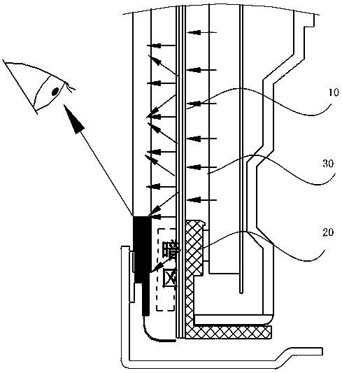
[0046] Such as Figure 9 As shown, the difference from Embodiment 1 is that the film edge protrusion 6031 of the second optical film 603 , the film edge protrusion 6021 of the first optical film 602 , and the film edge protrusion 6011 of the brightness enhancement film 601 and the protruding portion 6041 of the film edge of the third optical film 604 sequentially form a staggered layer structure interlaced with each other. Wherein, the film edge protrusion 6011 of the incremental film 601 is the same shape and size as the film edge protrusion 6031 of the second optical film 603, and the film edge protrusion 6021 of the first optical film 602 is the same as the third optical film edge protrusion 6021. The diaphragm edge protrusions 6041 of the diaphragm 604 are identical in shape and size.

[0047] Further, the film edge protrusion 6011 of the incremental film 601 is larger in area than the film edge protrusion 6021 of the first optical film 602 .

[0048] On the one hand, th...

Embodiment 3

[0051] Such as Figure 10 As shown, the same as the second embodiment, the film edge protrusion 6031 of the second optical film 603, the film edge protrusion 6021 of the first optical film 602, and the film edge protrusion 6011 of the brightness enhancement film 601 and the protruding portion 6041 of the film edge of the third optical film 604 sequentially form a staggered layer structure interlaced with each other. Wherein, the film edge protrusion 6011 of the incremental film 601 is the same shape and size as the film edge protrusion 6031 of the second optical film 603, and the film edge protrusion 6021 of the first optical film 602 is the same as the third optical film edge protrusion 6021. The diaphragm edge protrusions 6041 of the diaphragm 604 are identical in shape and size.

[0052] The difference from the second embodiment is that the film edge protrusion 6011 of the incremental film 601 is smaller in area than the film edge protrusion 6021 of the first optical film ...


PUM


Abstract

The invention provides a backlight module and liquid crystal display equipment. The backlight module comprises a fixing frame and optical membrane sets. The fixing frame comprises a side wall and a supporting arm extending in the vertical direction of the side wall. The upper surface of the supporting arm is provided with membrane fixing parts. Each optical membrane set comprises a brightening film and a first optical membrane, wherein the first optical membrane is arranged on the side, close to the fixing frame, of the brightening film and is adjacent to the brightening film. Each optical membrane is provided with a membrane edge protruding part. The optical membrane sets are matched with the membrane fixing parts through the membrane edge protruding parts to be fixed to the fixing frame. Parts, on the membrane edge protruding parts, of the brightening films and the first optical membranes do not overlap. The problem of shadow display in a visual area is reduced..

Description

technical field [0001] The invention relates to the technical field of liquid crystal display, in particular to a backlight module and a liquid crystal display device. Background technique [0002] The liquid crystal display device includes a liquid crystal panel and a backlight module that provides a light source for the liquid crystal panel. The backlight module includes a point light source (such as: an LED light-emitting chip excites a light conversion material to emit light), and a light homogenization treatment for the light path of the point light source. Optical components (such as: light guide plate, optical film, etc.) and fixing components (backlight and plastic frame, etc.) that provide fixing and supporting functions. [0003] In the prior art, in order to narrow the frame of the liquid crystal display device and reduce the frame space reserved for the diaphragm lugs, the technical solution of placing the diaphragm on top is usually adopted, for example: the dia...

Claims


Application Information

Patent Timeline
Patent Type & Authority Patents(China)
IPC IPC(8): G02F1/13357
Inventor 刘敏胡小龙
Owner HISENSE VISUAL TECH CO LTD
Why Eureka
Try Eureka