Low leakage reactance power transformer with current limiting reactor function

A technology of power transformers and current-limiting reactors, applied in the direction of transformer/inductor cores, etc., to achieve the effect of high short-circuit level and large short-circuit current

Active Publication Date: 2016-08-31
SHANGHAI UNIVERSITY OF ELECTRIC POWER
View PDF8 Cites 6 Cited by
  • Summary
  • Abstract
  • Description
  • Claims
  • Application Information

AI Technical Summary

Problems solved by technology

[0003] The invention aims at the problem of changing the number of windings on the low-voltage side of the high-impedance transformer used as a transformer under normal conditions and used as a high-impedance short-circuit reactance under fault conditions, and proposes a low-voltage transformer with the function of a current-limiting reactor. Leakage reactance power transformers have small reactance during normal operation and have little impact on system v

Method used


Image

  • Low leakage reactance power transformer with current limiting reactor function

Examples


Example Embodiment

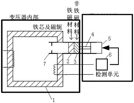
[0010] The conventional components of power transformers include high-voltage and low-voltage coils and iron cores. In order to realize two structures of transformers and short-circuit reactors, special iron core structures are designed, such as figure 1 The structure diagram of a low leakage reactance power transformer with the function of a current-limiting reactor is shown. The iron core is composed of two parts, one is an unclosed iron core ring 1, and the other is a movable combined iron core block, combined iron The core block is formed by the iron core block 2 and a marble core 3 of the same height or other non-magnetic materials that are not easily deformed. The core block 2 and the other part of the iron core block are combined together. The core ring 1 is combined into a completely closed iron core. The combined core block is placed in the motion track 7 with a limit card. The height of the combined core block matches the width of the motion track, and the pushing stru...


PUM


Abstract

The invention relates to a low leakage reactance power transformer with a current limiting reactor function; an iron core comprises a non-close iron core ring and a movable composite iron core block; the composite iron core block is formed by bonding the iron core block with a core in parallel, wherein the core is made of non-magnetic conductive material; a low voltage coil end is connected with a current detection unit; the current detection unit outputs a signal so as to control a push structure to move; the push structure uses a push rod to push the composite iron core block to move in a running track; the iron core block in the composite iron core block moves to the gap of the non-close iron core ring, and is combined with the non-close iron core ring, thus forming a complete closed iron core to carry out transformer works; the core of the composite iron core block moves to the gap of the non-close iron core ring, thus changing magnetic resistance, and changing external performance of the electric equipment; the low leakage reactance power transformer serves as the transformer under normal conditions, and serves as a short circuit reactor under fault conditions; the winding quantity in the low voltage side cannot be changed when the low leakage reactance power transformer serves as the reactor, and the short circuit level is very high, thus bearing vary large short circuit current.

Description

technical field [0001] The invention relates to electric equipment, in particular to a low leakage reactance power transformer with the function of a current-limiting reactor. Background technique [0002] In the current power distribution network, the short-circuit current is getting bigger and bigger, and in some places, the short-circuit current even exceeds the breaking capacity of the circuit breaker. Therefore, the power distribution system needs to limit the short-circuit current. At present, in addition to installing a current limiter in the distribution network, a reasonable wiring method and operation method are also used to reduce the short-circuit current. But another common method of limiting short-circuit current is to use high-impedance distribution transformers. This type of transformer has many structures, but each has different advantages and disadvantages (Document 1: Domestic transformer manufacturers, Kang Aihua of Baoding Tianwei Baobian, etc., "Desig...

Claims


Application Information

Patent Timeline
IPC IPC(8): H01F27/24
CPCH01F27/24
Inventor 淡淑恒傅晓飞刘建华
Owner SHANGHAI UNIVERSITY OF ELECTRIC POWER
Why Eureka
Try Eureka