Front electrode of solar cell

A technology of solar cells and front electrodes, which is applied in the field of solar cells, can solve the problems of being unable to adapt to the high-resistance dense grid technology, restricting the photoelectric conversion efficiency of cells, and increasing the cost of industrialization, so as to reduce the area, increase the injection, increase the open circuit voltage and Effect of short circuit current

Active Publication Date: 2013-12-18
陕西众森电能科技有限公司
View PDF6 Cites 18 Cited by
  • Summary
  • Abstract
  • Description
  • Claims
  • Application Information

AI Technical Summary

Problems solved by technology

Among them, screen printing is currently the main electrode production method, but it is difficult to make the width of the screen printing fine grid line less than 80 microns, and the mainstream equipment can only achieve 80-120 microns, so that the shading area of ​​the front electrode reaches 5-8%. , which restricts the further improvement of the photoelectric conversion efficiency of the battery
[0003] Patent CN101483199A provides a new electrode structure, which uses conductive metal wires with a diameter of 0.1-0.17 mm as bus grid lines, cancels thin grid lines, increases the number of main grid lines, and reduces the shading area of ​​about 3 mm width , which can improve the conversion efficiency of solar cells. The production method is to print silver paste on the front of the battery using a conventional screen printing process to make evenly distributed dot electrodes. The area of ​​the dot electrodes is greater than 1 square millimeter, and then weld the wires point by point. At this point, however, this process is complex and time-consuming, which will increase the cost of industrialization, and the solder joints are too large to adapt to the current high-resistance dense gate process
[0004] Patent CN102214729A provides a method for making front electrodes, which is obtained by bonding thin metal wires to the surface of silicon wafers with silver paste and sintering. The scheme greatly reduces the shading of the front, but because the thick metal wire with a diameter greater than 30 microns cannot be reliably sintered to the surface of the silicon wafer through the silver paste, the wire that is too thin will increase the series resistance

Method used


Image

  • Front electrode of solar cell
  • Front electrode of solar cell
  • Front electrode of solar cell

Examples


Embodiment Construction

[0032] The present invention will be described in detail below in conjunction with the accompanying drawings and specific embodiments, where the schematic embodiments and descriptions of the present invention are only used to explain the present invention, but not to limit the present invention.

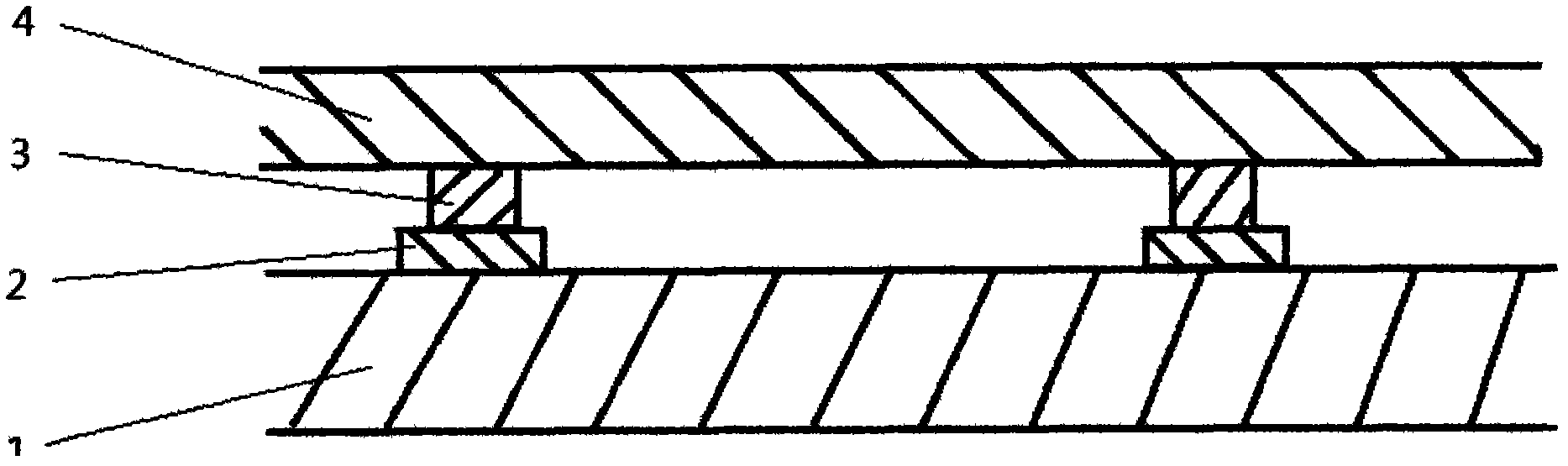
[0033] Such as figure 1 Shown is a partial schematic diagram of a solar cell bridge structure electrode structure of the present invention, a solar cell front electrode, including a semiconductor base 1, and dot-shaped electrodes 2 are regularly distributed on the semiconductor base 1, and the tops of the dot-shaped electrodes 2 are fixed with The connection part, the other end of the connection part is connected with a metal wire 4, and the metal wire 4 connects the point electrodes 2 in series along the row direction.

[0034] Such as figure 2 , image 3 Shown is a schematic diagram of the local area effect of a point contact electrode provided by the present invention. The poi...


PUM


Abstract

The invention relates to a point-contact front electrode structure of a solar cell. The front electrode structure is a bridge structure. The bridge structure comprises a bridge foundation, bridge piers and a bridge girder; the bridge foundation is weldable, silver paste or nickel paste is sintered to form the bridge foundation, and the bridge foundation is in excellent ohmic contact with a semiconductor of a substrate; solder paste is melted by heat to form the bridge piers, and the bridge girder can be conductively and mechanically connected with the bridge foundation by the bridge piers; the bridge girder comprises conducting metal wires, and currents of the various bridge piers can be gathered and led out by the aid of the bridge girder. The front electrode structure has the advantages that points of a point-contact electrode can be connected with one another by the metal wires, so that the total area of an electrode region is reduced, photon-generated carriers which are composited with one another on the surface of the cell are effectively reduced, the illumination shielding area of the electrode can be effectively reduced owing to the suspended metal wires, light injection is effectively increased, an open-circuit voltage and a short-circuit current are increased, and the conversion efficiency of the solar cell is improved; consumption of expensive silver is reduced owing to the structure, and accordingly the production cost of the solar cell is lowered.

Description

technical field [0001] The invention relates to the field of solar cells, in particular to a solar cell front electrode structure. Background technique [0002] Crystalline silicon solar cells are the mainstream solar cells at present. The production process is as follows: de-damaging layer texture, diffusion, phosphorus-silicon glass removal, peripheral etching, PECVD deposition of silicon nitride passivation anti-reflection film, screen printing front and back Electrodes, front and back electrodes are co-sintered. Among them, screen printing is currently the main electrode production method, but it is difficult to make the width of the screen printing fine grid line less than 80 microns, and the mainstream equipment can only achieve 80-120 microns, so that the shading area of ​​the front electrode reaches 5-8%. , restricting the further improvement of the photoelectric conversion efficiency of the cell. [0003] Patent CN101483199A provides a new electrode structure, whi...

Claims


Application Information

Patent Timeline
Patent Type & Authority Applications(China)
IPC IPC(8): H01L31/0224
Inventor 黄国保
Owner 陕西众森电能科技有限公司
Why Eureka
Try Eureka