Method of manufacturing trench gate super junction power device

A technology of power devices and manufacturing methods, applied in semiconductor/solid-state device manufacturing, semiconductor devices, electrical components, etc., can solve problems such as the influence of the lateral size of the accumulation area, the variation of device turn-on voltage and conduction voltage drop, and achieve the elimination of sleeve The problem of alignment deviation and the effect of preventing alignment deviation

Active Publication Date: 2016-08-31
SHANGHAI HUAHONG GRACE SEMICON MFG CORP
View PDF5 Cites 0 Cited by
  • Summary
  • Abstract
  • Description
  • Claims
  • Application Information

AI Technical Summary

Problems solved by technology

[0013] figure 2 Although the trench gate structure shown can reduce the size of the device, in the actual process, whether the P-type column 3 is formed by multi-layer epitaxy or epitaxial filling, because the P-type column 3 and the trench gate, that is, the polysilicon gate 6, are two Sub-lithography formation, registration deviation in the process will lead to the situation that the P-type pillar 3 affects the accumulation area of ​​the trench gate; the accumulation area of ​​the trench gate is located at the bottom of the P-type body region 5 and is covered by the side of the polysilicon gate 6 When there is a misregistration between the N-type epitaxial layer 2, the P-type pillar 3 and the trench gate, the lateral size of the accumulation region will be affected, which will deteriorate the turn-on voltage and turn-on voltage drop of the device

Method used


Image

  • Method of manufacturing trench gate super junction power device
  • Method of manufacturing trench gate super junction power device
  • Method of manufacturing trench gate super junction power device

Examples


Embodiment Construction

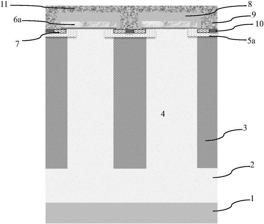
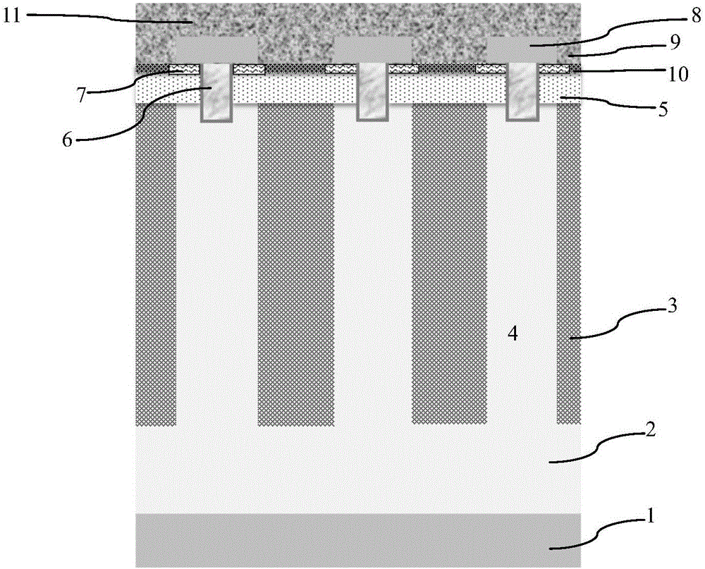
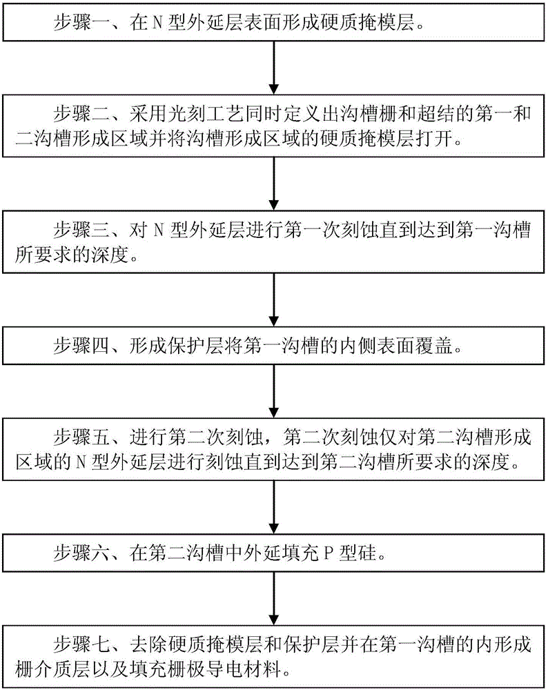
[0042] Such as image 3 Shown is the flow chart of the manufacturing method of the trench gate super junction power device according to the embodiment of the present invention; as Figure 4A to Figure 4N Shown is a schematic diagram of the device structure in each step of the manufacturing method of the trench-gate super-junction power device in the embodiment of the present invention. The manufacturing method of the trench-gate super-junction power device in the embodiment of the present invention includes the following steps:

[0043] Step 1, such as Figure 4AAs shown, a semiconductor substrate 1 is provided, and an N-type epitaxial layer 2 is formed on the surface of the semiconductor substrate 1 . In the embodiment of the present invention, the semiconductor substrate 1 is a silicon substrate, and the N-type epitaxial layer 2 is an N-type silicon epitaxial layer; in other embodiments, the semiconductor substrate 1 can also use other semiconductor materials.

[0044] Suc...


PUM


Abstract

The invention discloses a method of manufacturing a trench gate super junction power device. The method comprises steps: a hard mask layer is formed on the surface of an N-type epitaxial layer; a photoetching process is adopted to simultaneously define a first trench forming area and a second trench forming area of the trench gate and the super junction; first-time etching is carried out on the epitaxial layer until reaching the depth required by the first trench; a protective layer is formed to cover the inner-side surface of the first trench; second-time etching is carried out on the N-type epitaxial layer, wherein the second-time etching only etches the N-type epitaxial layer in the second trench forming area until reaching the depth required by the second trench; epitaxial filling of P-type silicon is carried out in the second trench; and the hard mask layer and the protective layer are removed and a gate dielectric layer is formed in the first trench and a gate conductive material is filled. Registration deviation between the trench gate and a P-type column can be prevented, the process stability can be improved, turn-on voltage and forward voltage drop of the device can be more uniform, and the size of the super junction unit can be smaller.

Description

technical field [0001] The invention relates to a method for manufacturing a semiconductor integrated circuit, in particular to a method for manufacturing a trench gate superjunction (superjunction) power device. Background technique [0002] The super junction structure is composed of alternately arranged N-type pillars and P-type pillars. If the superjunction structure is used to replace the N-type drift region in the vertical double-diffused MOS transistor (Vertical Double-diffused Metal-Oxide-Semiconductor, VDMOS) device, the conduction path is provided through the N-type column in the conduction state, and when the conduction The P-type column does not provide a conduction path; in the off state, the PN column jointly bears the reverse bias voltage, forming a super-junction metal-oxide-semiconductor field-effect transistor (Metal-Oxide-Semiconductor Field-Effect Transistor, MOSFET). The super-junction MOSFET can greatly reduce the on-resistance of the device by using a...

Claims


Application Information

Patent Timeline
Patent Type & Authority Applications(China)
IPC IPC(8): H01L21/336H01L29/78H01L29/06
CPCH01L29/0634H01L29/66734H01L29/7813
Inventor 柯行飞
Owner SHANGHAI HUAHONG GRACE SEMICON MFG CORP
Why Eureka
Try Eureka