Simulation signal optical fiber communication system with hot backup and use method thereof

An optical fiber communication system and analog signal technology, applied in the field of analog signal optical fiber communication system, can solve the problems of large bending radius loss of optical fiber, poor contact, dust on the optical fiber connection end face, etc., to ensure reliability and stability, and improve reliability. , easy to operate effect

Inactive Publication Date: 2016-08-31
NO 34 RES INST OF CHINA ELECTRONICS TECH GRP +2
View PDF6 Cites 2 Cited by
  • Summary
  • Abstract
  • Description
  • Claims
  • Application Information

AI Technical Summary

Problems solved by technology

However, there are many reasons for the existing analog optical fiber communication system to affect the reliability and stability of the system. For example, there is dust on the connection end face of the optical fiber connector, poor contact, and the bending radius of the optical fiber is too small, which will cause excessive loss and cause analog signal loss. Fiber optic communication system not working properly

Method used


Image

  • Simulation signal optical fiber communication system with hot backup and use method thereof
  • Simulation signal optical fiber communication system with hot backup and use method thereof
  • Simulation signal optical fiber communication system with hot backup and use method thereof

Examples


Embodiment 1

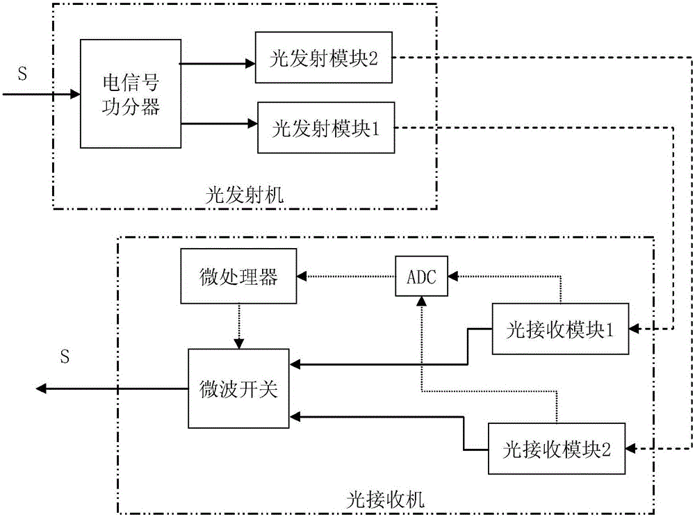
[0025] Embodiment 1 of the analog signal optical fiber communication system with hot backup is as figure 1 As shown in the figure, the short horizontal dotted line in the figure indicates the optical signal channel, the solid line indicates the analog signal channel, and the dotted dotted line indicates the electrical signal connection.

[0026] The optical transmitter in this example includes an electrical signal power divider and two identical optical transmitter modules that modulate analog signals into optical signals. One analog signal input is connected to the electrical signal power divider and divided into two analog signals, respectively Connect the optical transmitting module 1 and the optical transmitting module 2, and the output ends of the two optical transmitting modules are respectively connected to a transmission fiber; the optical receiver in this example includes two identical optical receiving modules 1 and 2, and an analog-to-digital conversion module (ADC)...

Embodiment 2

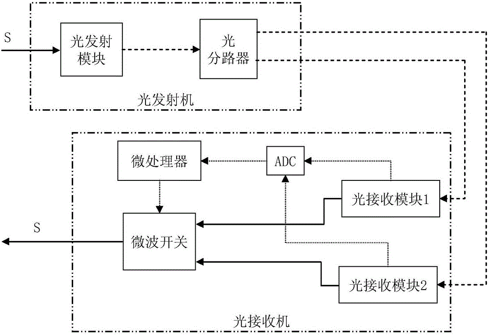
[0028] Embodiment 2 of the analog signal optical fiber communication system with hot backup is as figure 2 As shown, the connection line type is the same as that of Embodiment 1.

[0029] The optical transmitter in this example includes an optical transmission module and an optical splitter, the analog signal is connected to the optical transmission module, the output end of the optical transmission module is connected to the optical splitter to divide into two optical signals, and the optical splitter Each of the output ends is connected to a transmission fiber.

[0030] The structure of the optical receiver of this example is the same as that of the first embodiment.

Embodiment 3

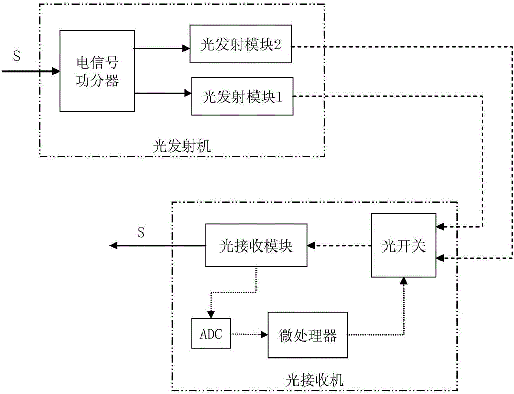
[0032] Embodiment 3 of the analog signal optical fiber communication system with hot backup is as image 3 As shown, the connection line type is the same as that of Embodiment 1.

[0033] The structure of the optical transmitter of this example is the same as that of the first embodiment.

[0034] The optical receiver of this example includes an optical switch, an optical receiving module, an analog-to-digital conversion module (ADC) and a microprocessor. Two transmission fibers are connected to the optical switch, and the output of the optical switch is connected to the optical receiving module. The output of the module is the final output analog signal of the system; the voltage of the sampling resistor connected to the light detector in the light receiving module in this example is connected to the microprocessor through analog-to-digital conversion, and the output of the microprocessor is connected to the optical switch, and the microprocessor real-time The received optic...


PUM


Abstract

The invention relates to a simulation signal optical fiber communication system with hot backup and a use method thereof. An optical transmitter of the system comprises one electric signal power divider and two optical transmitting modules, or comprises one optical transmitting module and one optical divider; and a receiver comprises two optical receiving modules, an AD module, a microprocessor and one microwave switch, or comprises one optical switch, one optical receiving module, an AD module and a microprocessor. The use method comprises the following steps: the optical transmitter inputs one path of simulation signal and outputs two paths of optical signals, the microprocessor of the optical receiver monitors the receiving optical power of the current optical receiving module according to the threshold of the lowest optical power value of reliable communication, switches the microwave switch or the optical switch, and selects one of the two optical signals with receiving optical power greater than or equal to the threshold value as a simulation signal for output. The system can be manually switched due to allocation of a display screen. The system can automatically produce a hot backup optical signal, and can select one path with normal transmission according to the receiving power, thus effectively ensuring communication reliability and stability.

Description

technical field [0001] The invention relates to optical fiber communication technology, in particular to an analog signal optical fiber communication system with hot backup and a using method thereof. Background technique [0002] Analog signal optical fiber transmission technology integrates optical fiber technology and high-frequency radio wave technology, and uses their respective advantages to realize large-capacity, low-cost, and long-distance wired transmission. Compared with radio wave communication, optical communication of analog signal has many advantages. First, optical communication of analog signal has a wide bandwidth, so its communication capacity is large; secondly, because optical signal has high frequency and strong directivity, it is difficult to Interference and interception, so the optical communication of analog signals has strong anti-interference ability and confidentiality. [0003] Because the optical communication of the analog signal has a large ...

Claims


Application Information

Patent Timeline
Patent Type & Authority Applications(China)
IPC IPC(8): H04B10/038H04B10/25H04B1/74
CPCH04B10/25H04B1/745H04B10/038
Inventor 黄锋锋岑少忠席虹标吴见平陈国帅胡彬陈君洪熊平戬谢嘉威谢宝荣曲会晨
Owner NO 34 RES INST OF CHINA ELECTRONICS TECH GRP
Why Eureka
Try Eureka