
Flow generator virtualization realization system and flow generator virtualization realization method based on SDN

A traffic generator and system implementation technology, applied in the field of communication, can solve problems such as mutual interference, inability to divide traffic, and influence of experimental results

Active Publication Date: 2016-08-31
CHONGQING UNIV OF POSTS & TELECOMM
View PDF2 Cites 19 Cited by
  • Summary
  • Abstract
  • Description
  • Claims
  • Application Information

AI Technical Summary

Problems solved by technology

However, when multiple experimental users need to operate the traffic generating device in parallel, the existing traffic generating system cannot effectively divide the traffic of different experimenters in the same experimental environment due to the different experimental contents.
This makes the experimental process of different users may interfere with each other, and ultimately affect the experimental results of each user

Method used


Image

  • Flow generator virtualization realization system and flow generator virtualization realization method based on SDN
  • Flow generator virtualization realization system and flow generator virtualization realization method based on SDN
  • Flow generator virtualization realization system and flow generator virtualization realization method based on SDN

Examples


Embodiment 1

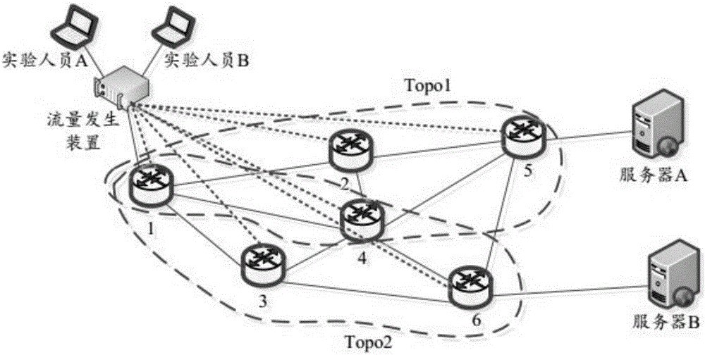
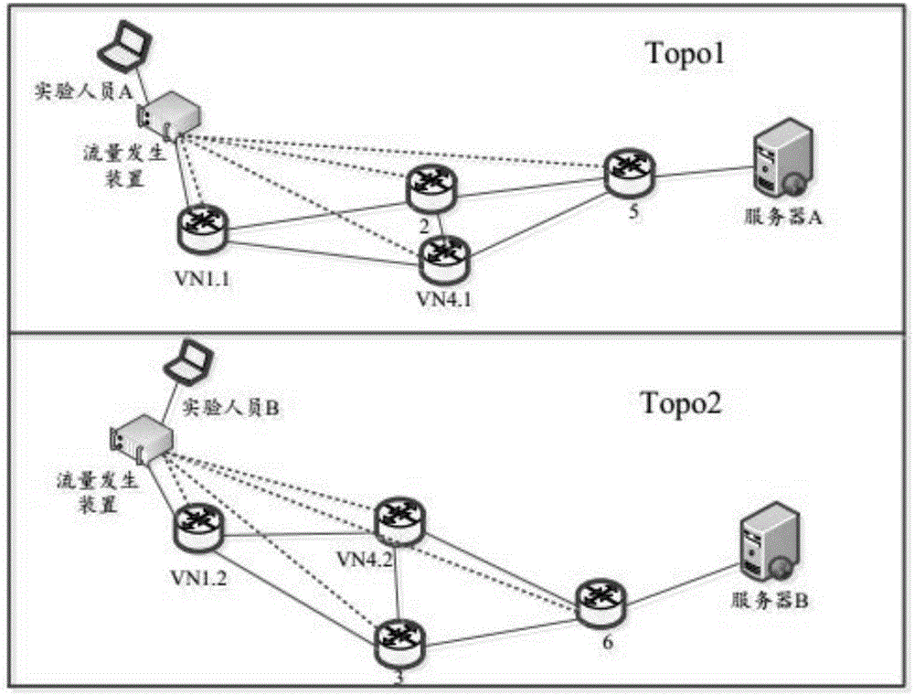
[0052] Such as figure 2 Shown is the implementation method framework of the SDN-based traffic generator virtualization of the present invention in which multiple experimenters operate in parallel, and experimenters A and B have different testing requirements. In this embodiment, the load pressure of the server is tested by customizing the topology. The experimenters consider that since a single path is selected in the test server load pressure experiment, the bandwidth may not be able to meet the continuously increasing data traffic, so multiple paths are selected as the test path. . As shown in the figure, there are 6 SDN switches in the network, the present invention and No. 1 switch, between the switch and the switch, the physical route between the switch and the server is marked with a solid line, and the control between the present invention and the SDN switch Lines are marked with dashed lines. This embodiment adopts figure 2 Network topology structure, after user A...

Embodiment 2

[0063] as attached Figure 4 Shown is a schematic diagram of multi-user and multi-device testing of the implementation method and device of the SDN-based traffic generator virtualization of the present invention. Experimenter C and experimenter D customize topology experiments according to their own experimental needs. Among them, experimenter C conducts a load stress test on server A, and experimenter D conducts a load stress test on switches 3 and 4 and server B. As shown in the figure, there are 6 SDN switches in the network, the present invention and No. 1 switch, between the switch and the switch, the physical route between the switch and the server is marked with a solid line, and the control between the present invention and the SDN switch Lines are marked with dashed lines. After users A and B customize the topology, the schematic diagram after virtualization and topology selection is as follows Figure 5 shown. Assume in this embodiment that No. 2 switch breaks do...

Embodiment 3

[0078] as attached Figure 7 Shown is a schematic diagram of the local network topology for multi-user testing of the implementation method of the SDN-based traffic generator virtualization of the present invention. As shown in the figure, there are 6 SDN switches in the network, the present invention and No. 1 and No. 2 switches, between the switch and the switch, the physical route between the switch and the server is marked with a solid line, and between the present invention and the SDN switch The control lines are marked with dotted lines. The specific implementation steps are as follows:

[0079] Step 701: The experimenter E and the experimenter F log into the system of the present invention at the same time, and the system is initially tested.

[0080] Step 702: Experimenter E and experimenter F customize the topology experiment according to the topology map presented by the user interface. Among them, experimenter E selects switches 2, 5, and 6, such as Figure 7 ...


PUM


Abstract

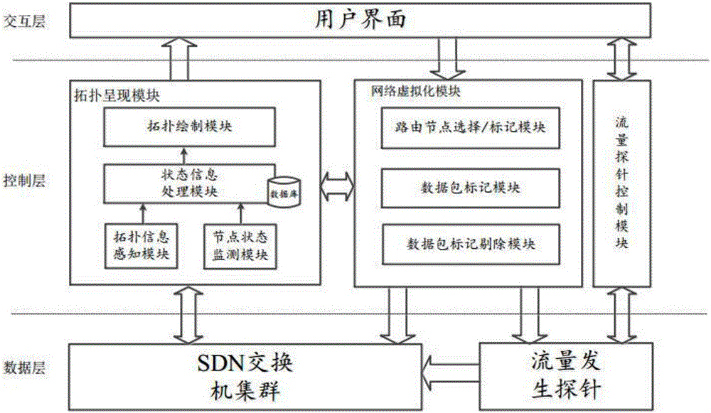
The invention provides a flow generator virtualization realization system and a flow generator virtualization realization method based on SDN, wherein the system and the method belong to the field of communication technology. The system comprises an interaction layer, a control layer and a data layer, wherein the control layer is composed of a topology representing module, a network virtualization module and a flow probe control module. A user performs self definition of a topology experiment according to a self requirement through network topology information which is sensed by the topology representing module. The network virtualization module constructs a flow table with a VLAN identification according to the user-defined topology and self specific characteristics, and transmits the flow table with the VLAN characteristic to an SDN exchange cluster. Network nodes with same VLAN identification form a logical virtual network. A data flows which are generated by the user re transmitted in respectively established virtual logical networks, thereby realizing data isolation of multiple experiment users in parallel operation, satisfying parallel operations of more experiment users, further improving network testing efficiency and reducing fund investment.

Description

technical field [0001] The invention belongs to the field of communications, and in particular relates to a system and method for realizing virtualization of a traffic generator based on SDN. Background technique [0002] In recent years, business fields such as mobile Internet, cloud computing, and big data have developed rapidly, and the scale of the network has continued to expand. Many problems have emerged in the traditional Internet, such as the high complexity of traditional network configuration. This shows that the network architecture of the traditional Internet needs to be innovated. Software Defined Networking (SDN) was born under this background. SDN is a brand-new network architecture. By separating the control plane of network equipment from the data plane, flexible control of the network is realized, which provides good support for the innovation of the core network and applications. At present, SDN technology has become a hot topic in global network resear...

Claims


Application Information

Patent Timeline
Patent Type & Authority Applications(China)
IPC IPC(8): H04L12/26H04L12/24
CPCH04L41/12H04L41/145H04L43/50
Inventor 曾帅盖绍聪王中莹范喜艳殷志坚郑派赵国锋唐红
Owner CHONGQING UNIV OF POSTS & TELECOMM
Learn More