Redundant drive system

A technology of drive system and oil supply system, which is applied in control systems, motor vehicles, electric vehicles, etc., can solve the problems of high cost and cost increase, and achieve the effect of low cost and improved failure reliability

Active Publication Date: 2016-08-31
ROLLS ROYCE DEUT LTD & CO KG
View PDF5 Cites 6 Cited by
  • Summary
  • Abstract
  • Description
  • Claims
  • Application Information

AI Technical Summary

Problems solved by technology

The disadvantage of this arrangement is the increased costs due to the additional winding system
At the same time, higher costs are incurred due to the higher number of inverters compared to group drives

Method used


Image

  • Redundant drive system
  • Redundant drive system
  • Redundant drive system

Examples


Embodiment Construction

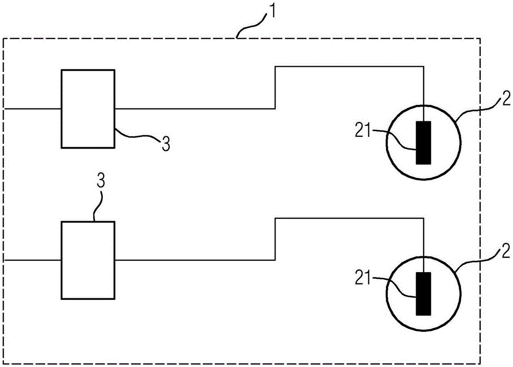
[0031] figure 1 A known drive system 1 is shown. It has two inverters 3 and two motors 2 . The engine 2 in turn contains a winding system 21 . The motors 2 are each fed via separate inverters 3 . Although motor 2 can be individually controlled open-loop or closed-loop by this arrangement, failure of inverter 3 has the result that motor 2 connected to it also fails and is therefore no longer able to provide torque. Group drives are also known, in which one inverter 3 supplies several motors 2 . Although this is better than figure 1 The configuration shown is less expensive, but the open-loop or closed-loop controllability of the individual motors 2 is lost in this group drive.

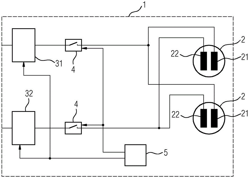
[0032] figure 2 A drive system 1 according to the invention is shown with two inverters 31 , 32 , two motors 2 , and a switch 4 at the output of the inverters 31 , 32 each and a central regulating device 5 . The central regulating device 5 can be implemented separately or integrated in one of ...


PUM


Abstract

The invention relates to a drive system (1). The drive system (1) has at least two inverters (3, 31, 32, 33) and at least two motors (2). Each of the motors (2) each of which comprising a stator and a rotor has at least one first coil system (21) and a second coil system (22) in the stator. Each first coil system (21) is connected to a first inverter (31) in an electrically conductive manner, and each second coil system (22) is connected to a second inverter (32) in an electrically conductive manner. The invention further relates to a method for the redundant operation of a drive system (1), wherein at least one motor exchanges electric energy with the second inverter (32) and / or one or more additional inverters (33) if the first inverter (31) fails.

Description

technical field [0001] The invention relates to a drive system, wherein the drive system has at least two inverters and at least two motors. The invention also discloses a method for the redundancy principle of the drive system. Background technique [0002] In electric drive technology the engine is used not only to drive the machine but also to accelerate or retard the vehicle. The motor is supplied with energy via the regulator of the power electronics. The power electronics serves as a regulator for the transmission of energy from the energy supply network to the engine in closed-loop control or open-loop control. For three-phase AC motors, such as synchronous or asynchronous motors, the inverter is used as a regulator for the power electronics. In many fields of application, an inverter is used here for each motor. This has the advantage that each of the multiple engines can be individually closed-loop controlled in terms of torque. In another more cost-effective v...

Claims


Application Information

Patent Timeline
Patent Type & Authority Applications(China)
IPC IPC(8): B60L3/00B60L3/04H02P25/22
CPCB60L3/0092B60L3/04H02P25/22H02M7/493B60L2200/10B60L2200/32B60L2200/44B60L2220/42B60L2220/56B60L2220/58B60L2240/423B60L2220/50Y02P90/60B60L3/003B60L2200/26Y02T10/64H02M1/325B64D27/24H02P3/22H02P5/74H02P27/06
Inventor 汉斯·弗里德里希·斯特凡尼
Owner ROLLS ROYCE DEUT LTD & CO KG
Why Eureka
Try Eureka