
Method for operating a two-stroke otto engine

An Otto engine, two-stroke technology, applied in the direction of engine components, engine control, combustion engine, etc., to achieve uniform heat distribution and reduce the risk of carbon deposition

Inactive Publication Date: 2016-08-31
罗兰・柯克伯格
View PDF6 Cites 3 Cited by
  • Summary
  • Abstract
  • Description
  • Claims
  • Application Information

AI Technical Summary

Problems solved by technology

In addition, the introduction of fuel into the combustion chamber through the overflow channel is only related to the control time of the overflow channel, which determines the corresponding scavenging loss

Method used


Image

  • Method for operating a two-stroke otto engine
  • Method for operating a two-stroke otto engine
  • Method for operating a two-stroke otto engine

Examples


Embodiment Construction

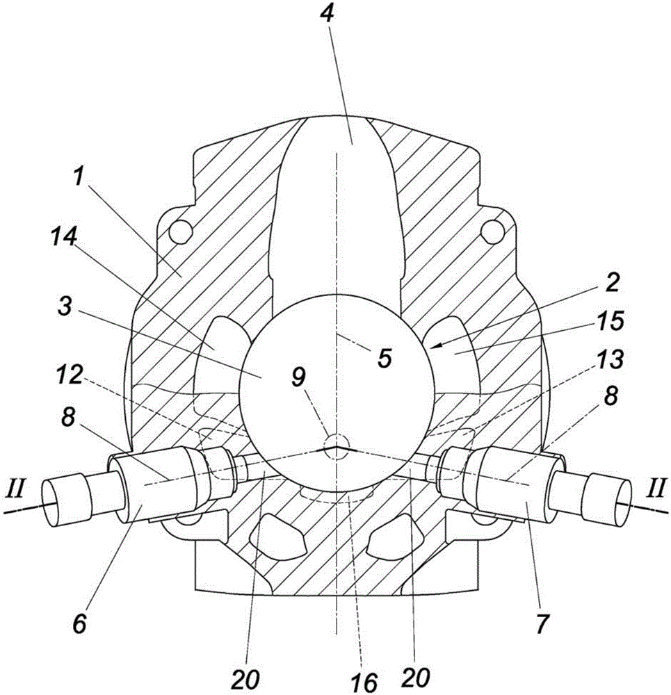
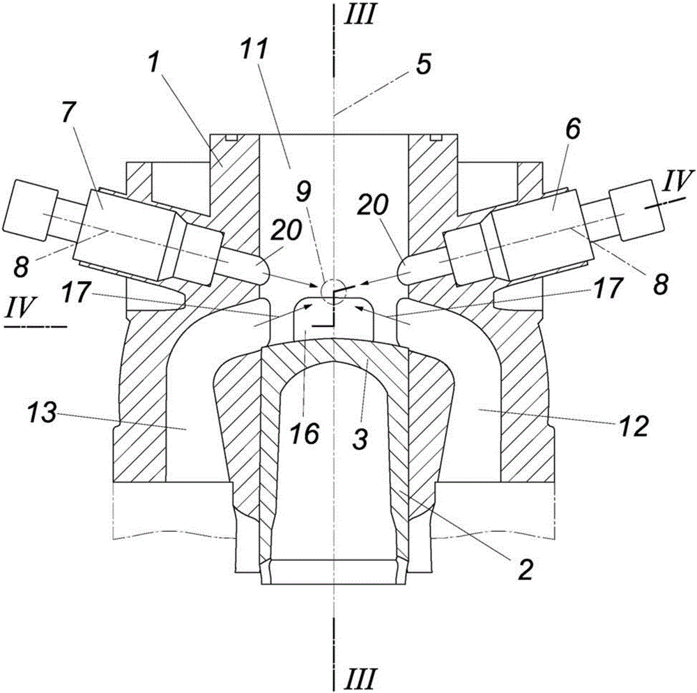
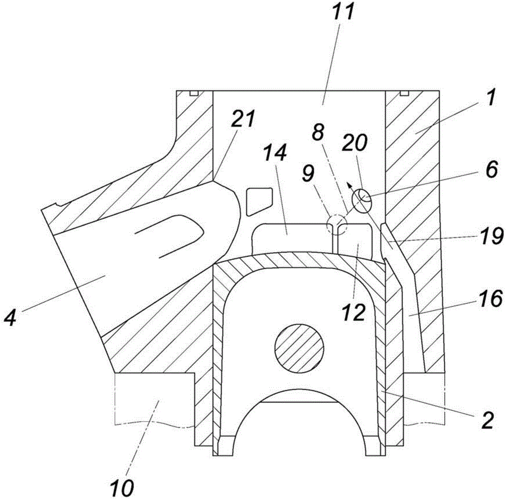
[0016] Only one cylinder 1 of the engine block of the two-stroke Otto engine is shown in the drawing without a cylinder head. The piston shown in the bottom dead center position is marked 2 and has a piston crown 3 . On the side of the cylinder opposite the exhaust duct 4 there are two injection nozzles 6, 7 symmetrical with respect to the diametric plane 5 defined by the axis of the exhaust duct 4, whose nozzle axes 8 intersect in the diametric plane 5, i.e. intersect at the intersection point 9, which is located above the piston crown 3 in the bottom dead center position of the piston 2 shown, as in particular from figure 2 It can be seen in.

[0017] Between the crankcase 10 and the combustion chamber 11 of the cylinder 1 indicated only by dashed lines, there are transfer channels 12 , 13 and 14 , 15 arranged opposite each other in pairs and arranged symmetrically with respect to the diametrical plane 5 . In addition, the cylinder 1 has a transfer channel diametrically o...


PUM


Abstract

The invention relates to a method for operating a two-stroke Otto engine comprising at least one cylinder (1) that receives a piston (2); a crankcase (10) which is fluidically connected to the combustion chamber (11) of said cylinder (1) by means of overflow channels (12, 13, 14, 15, 16) on either side of a diameter plane (5) of the cylinder (1) which is determined by the axis of an outlet channel (4); and two fuel injection nozzles (6, 7) that are arranged either side of said diameter plane (5) and whose nozzle axes (8) extend, in the bottom-dead centre position of the piston (2), above the piston base (3) and at least approximately in the outlet flow direction (17, 18) of the overflow channels (12, 14: 13, 15) each provided on the opposite sides of said diameter plane (5), the fuel being injected with reduced momentum into the combustion chamber (11) of the cylinder (1) via only one of the injection nozzles (6, 7) per working cycle when idling and in the lower part-load range.

Description

technical field [0001] The invention relates to a method for operating a two-stroke-Otto engine having at least one cylinder accommodating a piston and having a crankcase passing on both sides of a cylinder diameter plane defined by the axis of the exhaust passage The overflow channel is in fluid communication with the combustion chamber of the cylinder, which has two injection nozzles for fuel arranged on both sides of the diametrical plane, the nozzle axes of which are above the piston crown and at least approximately along the respective The transfer channels arranged on opposite sides of the diametrical plane extend in the direction of outflow, wherein fuel is injected per working cycle at least through one of the injection nozzles at least in idling mode. Background technique [0002] In order to be able to achieve a corresponding evaporation of fuel on the hot piston crown of a two-stroke engine, it is known (EP 0302045A2) to inject fuel onto the piston crown by means ...

Claims


Application Information

Patent Timeline
IPC IPC(8): F02D41/30F02D41/34F02F1/22F02B23/10
CPCF02B23/104F02B25/14F02B25/18F02M69/045F02M69/10F02D41/08F02D41/3094F02D41/345F02D2041/389F02D2400/04F02F1/22F02B33/04Y02T10/12Y02T10/40
Inventor 罗兰.柯克伯格
Owner 罗兰・柯克伯格
Learn More