Shear gauge system and use method thereof

A technology of sizing machine and reducer, which is applied to the accessories of shearing machine, shearing device, metal rolling, etc., can solve the problems of inaccurate sizing, heavy maintenance work, complex structure of sizing machine, etc.

Active Publication Date: 2016-09-07
SHANDONG IRON & STEEL CO LTD
View PDF8 Cites 2 Cited by
  • Summary
  • Abstract
  • Description
  • Claims
  • Application Information

AI Technical Summary

Problems solved by technology

[0005] In the embodiment of the present invention, a system of a sizing machine and its use method are provided to solve the problems in the prior art such as inaccurate sizing, complex structure of the sizing machine, high cost, easy wear and heavy maintenance workload, etc.

Method used


Image

  • Shear gauge system and use method thereof
  • Shear gauge system and use method thereof
  • Shear gauge system and use method thereof

Examples


Embodiment 1

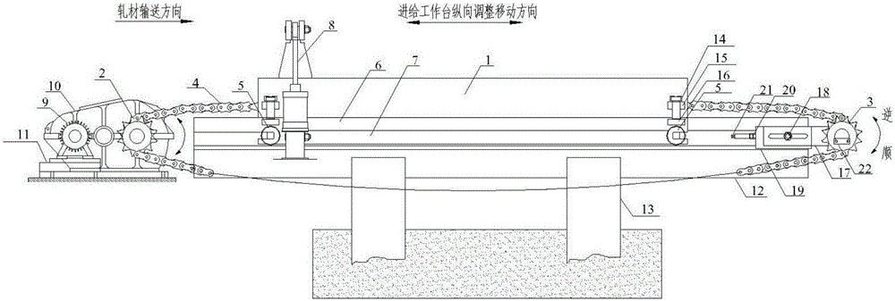
[0046] see figure 1 , is a schematic diagram of the general assembly structure of a sizing machine system provided by an embodiment of the present invention, including a motor 9, a reducer 10, a sprocket mechanism, a bearing mechanism, a feed table 1, a sliding screw mechanism and a sizing machine 8.

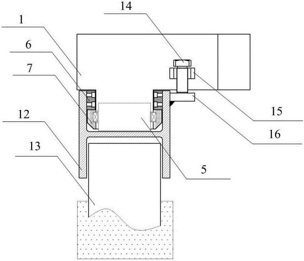
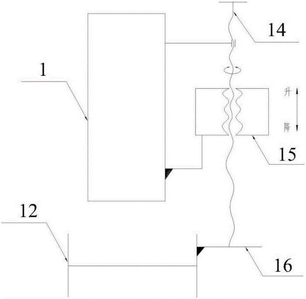
[0047] In order to carry the feed table 1, the carrying mechanism is set on the underside of the feed table 1, see figure 2 , the carrying mechanism is arranged below the feed table 1 and fixed to the ground, and its structure includes: a guide groove 12 , a supporting plate 16 and an upper friction plate 6 . The guide trough 12 can be fixed to the ground through uprights 13, and the number of the uprights 13 is greater than or equal to 2, which are evenly distributed under the guide trough. In the embodiment of the present invention, the guide groove 12 is designed as an H-shaped steel guide groove, and the column 13 is designed as an H-shaped steel column. Of course, the gui...

Embodiment 2

[0091] see Figure 8 , is a structural schematic diagram of another sizing machine system provided by an embodiment of the present invention, including a feed table 1, a sprocket mechanism, a bearing mechanism, a sliding screw mechanism, and a sizing machine 8. The present embodiment and the first embodiment The difference is that, in this embodiment, two sizing machines are fixedly connected on the feed workbench 1, namely the first sizing machine 08 and the second sizing machine 008, along the feed workbench 1 The feed direction intervals are fixed on the feed table 1. Under normal working conditions, the baffle plate of the first sizing machine 08 is the first baffle plate, and the baffle plate of the second sizing machine 008 is the second baffle plate, and the first baffle plate cooperates with the cold shearing machine. Cut to length, its main function is to instantly absorb the initial kinetic energy of the dynamic double-length rolling piece from the upstream process,...


PUM

PropertyMeasurementUnit
tensile strengthaaaaaaaaaa
yield strengthaaaaaaaaaa
diameteraaaaaaaaaa

Abstract

The invention relates to a shear gauge system and a use method thereof. The shear gauge system comprises a feeding worktable, a chain wheel mechanism, a bearing mechanism, sliding screw mechanisms and a shear gauge, wherein the bearing mechanism comprises a guide groove, supporting plates and an upper friction plate; the feeding worktable is arranged on the guide groove in a slidable manner through vertical roll assemblies; a lower pressing plate is fixedly connected onto the feeding worktable; the upper surface of the lower pressing plate is in contact with the lower surface of the upper friction plate; each sliding screw mechanism comprises a welding nut fixed on the feeding worktable and a fastening bolt which are matched with each other, and the bottom of the fastening bolt is in contact with the corresponding supporting plate; the chain wheel mechanism comprises a roller chain and a first chain wheel and a second chain wheel which are meshed with the roller chain; and the shear gauge is fixedly connected onto the feeding worktable. During a use process, the sliding screw mechanisms are adjusted, so that the upper friction plate is matched with the lower pressing plate; high static friction force is provided, so that the shear gauge does not deflect under high-load impact, and the sizing precision is improved; and furthermore, the chain wheel mechanism has the advantages of high precision, abrasion-resistance, small spatial size and the like.

Description

technical field [0001] The invention relates to the technical field of steel rolling equipment, in particular to a sizing machine system and a method for using the same. Background technique [0002] In the field of steel rolling, products are produced according to the specified size, so that the production and use of steel can effectively save metal, and facilitate the organization of production, make full use of equipment potential, simplify packaging and facilitate transportation. The method of steel sizing varies with the scale of production, the degree of mechanization and automation, and the variety of steel. [0003] The sizing machine is a commonly used sizing device, which is located behind the cutting equipment such as cold shears or sawing machines, and is used in conjunction with the use of cold shears or sawing machines to achieve cut-to-length cutting of rolled pieces. The existing sizing machine mainly drives the gear bar device to translate along the roller ...

Claims


Application Information

Patent Timeline
Patent Type & Authority Applications(China)
IPC IPC(8): B21B15/00B23D33/10
CPCB21B15/0007B23D33/10
Inventor 李永峰李来中王莉
Owner SHANDONG IRON & STEEL CO LTD
Why Eureka
Try Eureka