Punching method for internal high pressure forming pipe fitting

A technology of internal high pressure and pipe fittings, which is applied in the field of punching of internal high pressure forming pipe fittings, can solve the problems of large punching cylinder size, reduce production efficiency, increase punching process, etc., achieve uniform force, improve punching accuracy, and overall smoothness Good results

Inactive Publication Date: 2016-09-07
BAOLONG ANHUI AUTO PARTS
View PDF5 Cites 8 Cited by
  • Summary
  • Abstract
  • Description
  • Claims
  • Application Information

AI Technical Summary

Problems solved by technology

[0004] 1. Since the punching is only supported by high-pressure liquid, a certain degree of indentation will inevitably occur at the edge of the blank punching, and the burrs on the inner surface of the pipe are difficult to remove.
[0005] 2. The larger the punching hole diameter, the greater the punching force required, the larger the tonnage of the punching cylinder, and the higher the cost
And limited by the limited space on the hydraulic forming machine, and the size of the punching cylinder is too large, it is generally difficult to punch out the holes on the lower mold, and an additional punching process is required
[0006] 3. Limited by the diameter of the hole material, the maximum diameter of the punch rod cannot exceed the diameter of the hole material, so that the force on the punch rod can reach 620MPa, which is close to the yield strength of the material, and the fatigue life of the punch is low. When replacing the punch, the mold needs to be removed , time-consuming
[0007] 4. After punching, the hole material will fall into the inner high pressure forming pipe fittings, which increases the follow-up cleaning work and reduces the production efficiency

Method used


Image

  • Punching method for internal high pressure forming pipe fitting
  • Punching method for internal high pressure forming pipe fitting

Examples


Embodiment Construction

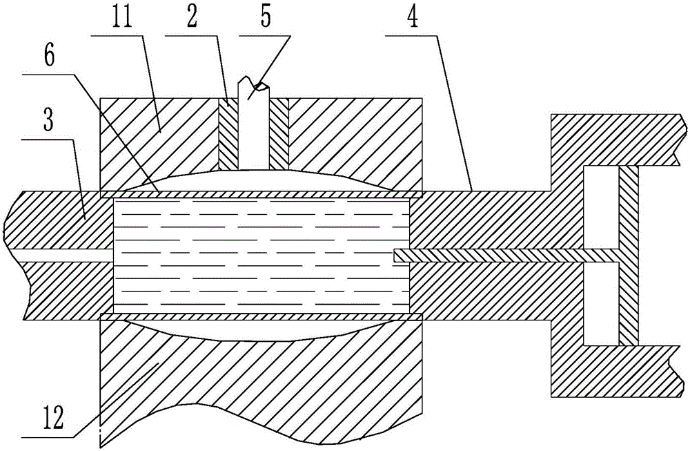
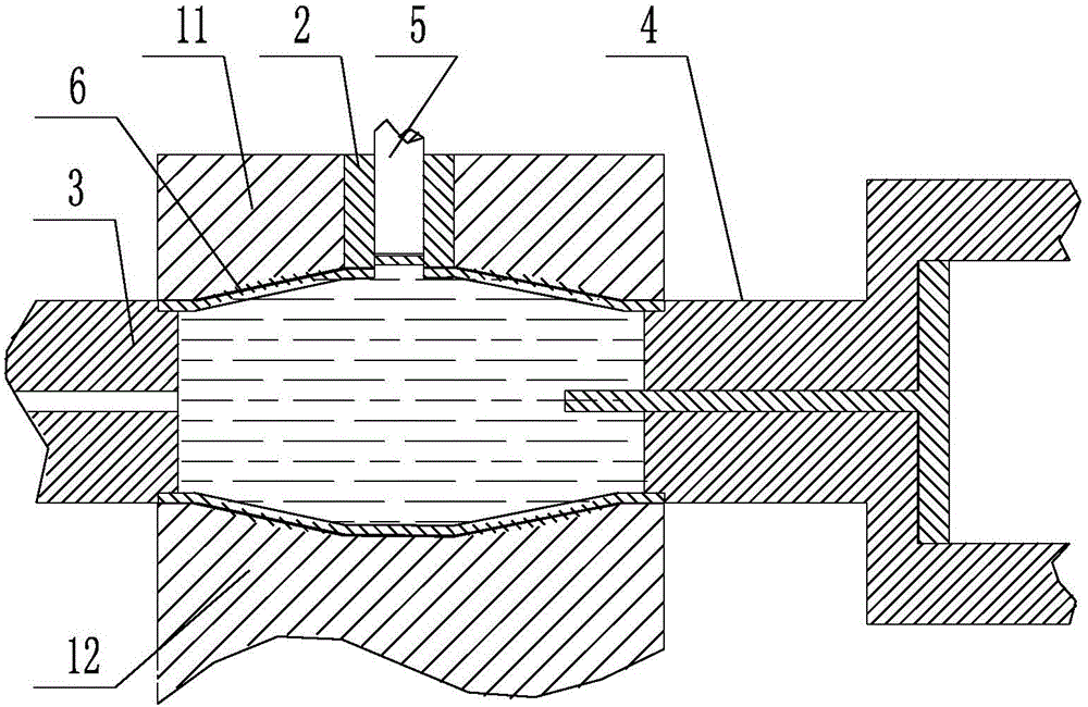
[0030] Such as figure 1 and 2 as shown, figure 1 It is a structural schematic diagram of the initial state of a punching device for internal high-pressure forming pipe fittings proposed by the present invention, figure 2 It is a structural schematic diagram of a punching device for internal high-pressure forming pipe fittings proposed by the present invention after the punching is completed.

[0031] The present invention proposes a punching method for internal high-pressure forming pipe fittings, which includes the following steps:

[0032] S1. Put the pipe to be punched into the mold cavity, make the part of the pipe to be punched at the punching station, inject liquid into the pipe, wherein the side wall of the mold cavity is provided with a punching hole, and the punching There is a limit stop in the hole;

[0033] S2. Increase the liquid pressure in the pipe to the first pressure threshold P1, so that the side wall of the pipe is against the limit stopper, wherein, P...


PUM


Abstract

The invention discloses a punching method for an internal high pressure forming pipe fitting. After internal high pressure forming, further setting of a punching tool is not required, a forming die is used for supporting, liquid pressure is utilized for applying a force on a punching portion, and therefore the punch portion is evenly stressed, and the punching precision is improved; the punching direction is from inside to outside, so that the product internal dent problem due to internal punching is completely solved; and at the same time, burrs generated during punching are located on the outer side of a workpiece and can be eliminated by subsequent simple polishing, and the overall finish degree of the product is good. The invention further discloses a device used for achieving the punching method for the internal high pressure forming pipe fitting, the punching method can be achieved through the optimal setting of the device, and therefore the applicability of the punching method is high assuringly, and the machining cost is lower.

Description

technical field [0001] The invention relates to the technical field of pipe fitting processing, in particular to a punching method for an internal high pressure forming pipe fitting. Background technique [0002] In the field of pipe fittings processing of automobile chassis, instrument panel bracket and other parts, internal high pressure forming is usually used for processing. In order to enable the pipe ring formed by internal high pressure to be assembled with other parts, several to a dozen holes are usually drilled on the pipe ring. The conventional processing method is to first shape the workpiece through internal high pressure, and then punch the formed workpiece through the method of punching holes in the mold. [0003] Such as figure 1 As shown, the internal high-pressure forming is to put a certain length of pipe ring into the mold, and under the action of internal liquid (water or oil) pressure, by controlling the liquid pressure and material flow, the pipe rin...

Claims


Application Information

Patent Timeline
Patent Type & Authority Applications(China)
IPC IPC(8): B21D26/035
CPCB21D26/035
Inventor 陈旭林刘兵郑玉磊陈绍明邓小波罗强丰杨杰
Owner BAOLONG ANHUI AUTO PARTS
Why Eureka
Try Eureka