Automatic locating device, bender system employing automatic locating device and plate bending method

An automatic positioning and bending machine technology, applied in the field of bending machines, can solve the problems of inflexible use, high manufacturing cost, inconvenient promotion and application, etc., and achieve the effects of flexible use, reduced energy consumption, and improved bending efficiency

Active Publication Date: 2016-09-07
JIANGSU HAIJIAN
View PDF12 Cites 10 Cited by
  • Summary
  • Abstract
  • Description
  • Claims
  • Application Information

AI Technical Summary

Problems solved by technology

[0007] The above-mentioned applications are all good methods for realizing automatic plate bending, which liberates the labor force to a certain extent, but the manufacturing costs of the above-mentioned applications are high, and the use is not flexible enough, so it is not easy to popularize and apply

Method used


Image

  • Automatic locating device, bender system employing automatic locating device and plate bending method
  • Automatic locating device, bender system employing automatic locating device and plate bending method
  • Automatic locating device, bender system employing automatic locating device and plate bending method

Examples


Embodiment 1

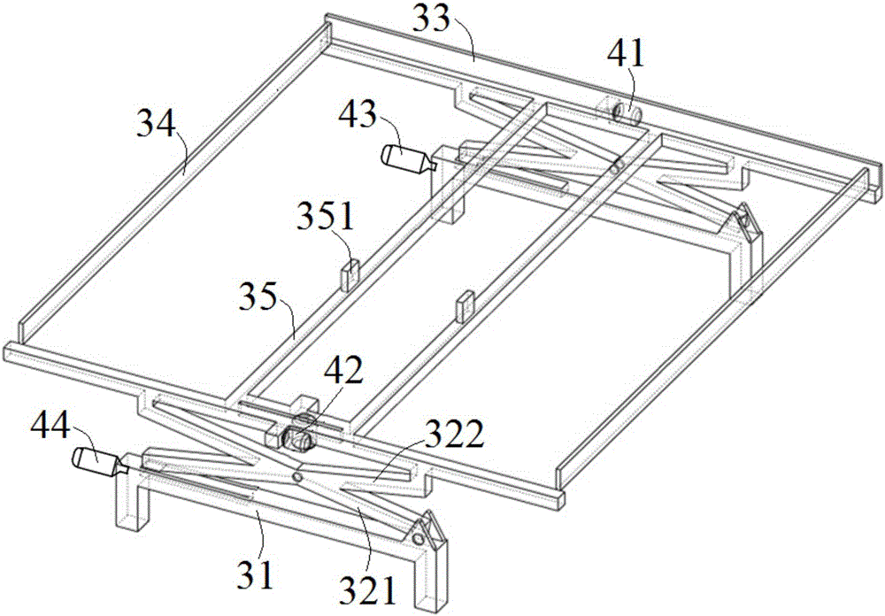
[0045] combine figure 2 , image 3 with Figure 4 , a kind of automatic positioning device of the present embodiment, comprises automatic elevating mechanism and workbench, and described automatic elevating mechanism comprises support 31, elevating frame, fixed plate 33, sliding plate 34 and slider guide rail 35, support 31, elevating frame , fixed plate 33, sliding plate 34 and slider guide rail 35 are all arranged in pairs, support 31 supports elevating frame, elevating frame is connected with fixed plate 33, fixed plate 33 and sliding plate 34 surround a square frame, two sliding plates 34 are opposite Set and can move along the length direction of the fixed plate 33; the two slider guide rails 35 are arranged in the middle of the fixed plate 33, and the slider guide rails 35 are parallel to the slide plate 34, and the slider guide rails 35 are provided with sliders 351, the slider 351 can move along the slider guide rail 35.

[0046] In the present embodiment, the two ...

Embodiment 2

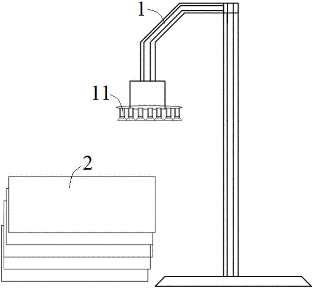
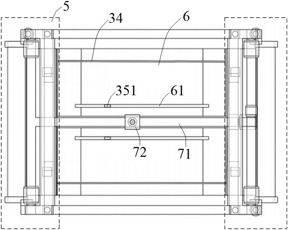
[0052] A bending machine system in this embodiment includes the automatic positioning device as described in Embodiment 1, and also includes figure 1 The shown automatic feeding mechanism and a bending machine 5, the automatic feeding mechanism includes a feeding manipulator 1, one end of the feeding manipulator 1 is provided with a suction cup group 11, and the suction cup group 11 is arranged in a circle by a plurality of suction cups . The bending machine 5 is arranged on the side perpendicular to the moving direction of the sliding block 351 of the automatic positioning device.

[0053] The structural block diagram of the control system and the electrical control schematic diagram of the present embodiment are as follows: Figure 5 with Image 6 As shown, the process of sheet metal bending is:

[0054] Step 1. The feeding manipulator 1 absorbs the workpiece 2 and puts it on the workbench plane 6;

[0055] Step 2, the servo motor controls the lifting frame to rise, and ...

Embodiment 3

[0062] A bending machine system of this embodiment is basically the same as that of Embodiment 1, the difference is that two bending machines 5 are provided in this embodiment, and the two bending machines 5 are respectively arranged on the automatic positioning device and the slide Block 351 moves both sides perpendicular to the direction.

[0063] The working process of this embodiment is as follows: first, the workpiece 2 is adsorbed by the loading manipulator 1 to the workbench, and placed on a certain area of ​​the workbench. When the feeding manipulator 1 absorbs the workpiece 2 to the workbench, the 3# servo motor 43 and the 4# servo motor 44 start at the same time, driving the automatic lifting mechanism to move upward until the automatic lifting mechanism completely fits the workbench. At this time, the sliding plate 34 The two sides of the workbench rise to the top of the workbench, and the height is slightly higher than the workbench plane 6 . The slider 351 is inse...


PUM


Abstract

The invention discloses an automatic locating device, a bender system employing the automatic locating device and a plate bending method and belongs to the technical field of benders. The automatic locating device comprises an automatic lifting mechanism and a worktable, wherein processing parts are placed on the plane of the worktable; the automatic lifting mechanism moves in the vertical direction and acts on the processing parts to realize locating of the processing parts in the horizontal direction; and the worktable is also provided with grabbing manipulators which realize locating of the processing parts in the vertical direction and rotation of the processing parts in the horizontal direction. The bender system is characterized in that benders are mounted on one side or two sides of the automatic locating device. A loading manipulator is utilized to grab the processing parts and convey the grabbed processing parts to the worktable, then left and right sliding plates and sliders of the automatic lifting mechanism are utilized to accurately locate the processing parts, and finally, the grabbing manipulators are used for realizing automatic rotation and multi-edge bending of the processing parts, so that the production efficiency can be remarkably improved, automation is realized, and the labor force is liberated from tedious work.

Description

technical field [0001] The present invention relates to the technical field of bending machines, and more specifically, relates to an automatic positioning device, a bending machine system using the positioning device and a sheet metal bending method. The present invention is used for automatic grabbing, Automatic positioning and feeding, automatic bending and automatic rotating multilateral bending. Background technique [0002] The sheet metal bending machine is a kind of forging machinery, which is mainly used in the sheet metal processing industry. The sheet metal bending machine can use simple molds to bend metal sheets in a straight line at various angles to obtain sheet metal parts with complex shapes. It is easy to operate and low in operating costs. The machine of choice for sheet metal processing is widely used. [0003] Sheet metal bending machine can be divided into mechanical bending machine and hydraulic bending machine according to its transmission form. At...

Claims


Application Information

Patent Timeline
Patent Type & Authority Applications(China)
IPC IPC(8): B21D43/00B21D43/18B21D5/00
CPCB21D5/00B21D43/003B21D43/18
Inventor 周郁明李绍铭徐龙淞
Owner JIANGSU HAIJIAN
Why Eureka
Try Eureka