
Star-shaped discharging valve with protecting structure

A protective structure and discharge valve technology, which is applied in cleaning devices, conveyor objects, loading/unloading, etc., can solve the problems of reducing the service life of equipment, aggravating rotor wear, and rotor locking, so as to prolong the service life and reduce locking. Chance of dying, avoiding the effect of clinging to death

Active Publication Date: 2016-09-07
TONGLING NONFERROUS XINGTONG ELECTROMECHANICAL MFG CO LTD
View PDF11 Cites 7 Cited by
  • Summary
  • Abstract
  • Description
  • Claims
  • Application Information

AI Technical Summary

Problems solved by technology

[0004] In the existing star-shaped discharge valve, several rectangular blades are welded on the rotating shaft to form the rotor. There is a gap between the rotor and the casing. When the gap between the rotor and the casing is too large, the star-shaped discharge valve Material leakage is easy to occur; even if the gap between the rotor and the casing is small enough, dust and powdery materials can easily infiltrate from the gap between the rotor and the casing under the long-term operation of the star discharge valve. And accumulate on the shaft of the rotor, not only aggravate the wear of the rotor, but even cause the rotor to lock up, reducing the service life of the equipment

Method used


Image

  • Star-shaped discharging valve with protecting structure
  • Star-shaped discharging valve with protecting structure
  • Star-shaped discharging valve with protecting structure

Examples


Embodiment Construction

[0019] In order to make the object, technical solution and advantages of the present invention clearer, the present invention will be further described in detail below in conjunction with the accompanying drawings and embodiments. It should be understood that the specific embodiments described here are only used to explain the present invention, not to limit the present invention.

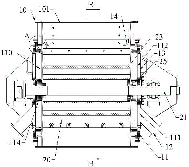
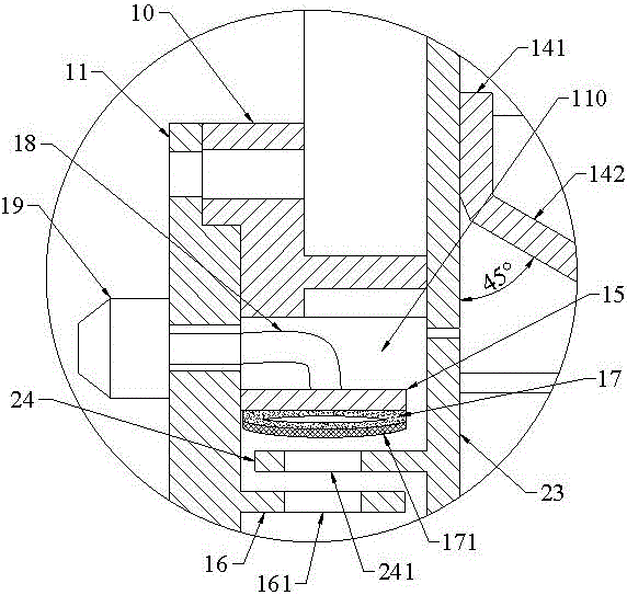
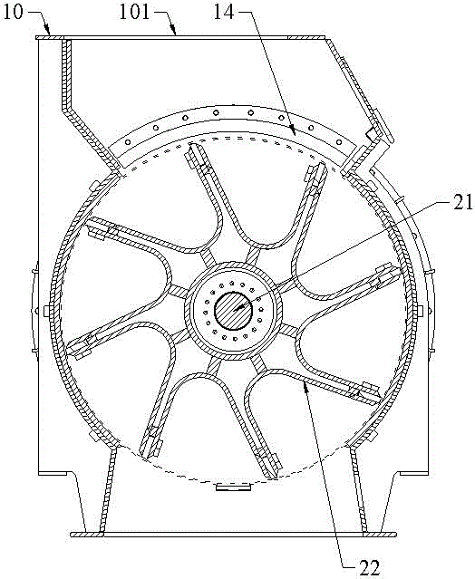
[0020] like figure 1 , figure 2 , Figure 4 , Figure 5 As shown, the star discharge valve with a protective structure includes a housing 10, a rotor 20 and a flange cover 11. The inner cavity of the housing 10 is cylindrical and the two sides of the housing 10 are open structures. , the housing 10 and the rotor 20 are fixedly connected by a flange cover 11, the rotor 20 includes a rotating shaft 21, and a plurality of blades 22 with a U-shaped cross section are arranged around the rotating shaft 21, and the blades 22 are arranged on the housing 10 Inner cavity, the bottom of the blade 22 is a...


PUM


Abstract

The invention relates to a star-shaped discharging valve with a protecting structure. The star-shaped discharging valve with the protecting structure comprises a shell, a rotor and a flange cover, wherein the rotor comprises a rotating shaft; a plurality of blades with U-shaped cross sections are arranged on the periphery of the rotating shaft; circular side plates are arranged at the left side and right side of each blade; an expansion sleeve matched with the rotating shaft is arranged in the center of each side plate; a buffering cavity is arranged between each side plate and the flange cover; a cylindrical inner protecting sleeve is arranged in the buffering cavity; a cylindrical upper protecting sleeve is arranged at the outer side of the inner protecting sleeve; a cylindrical lower protecting sleeve is arranged at the inner side of the inner protecting sleeve; a mounting hole matched with the rotating shaft is arranged in the center of the flange cover; and a shaft sleeve matched with the expansion sleeve is arranged at the outer side of the mounting hole. The star-shaped discharging valve with the protecting structure has the beneficial effects that dust and powdery materials on the discharging valve are convenient and fast to clean through matching of an air bag and a hairbrush layer under the multiple protection effect of a material blocking plate, the upper protecting sleeve, the lower protecting sleeve, the inner protecting sleeve and the shaft sleeve, the cleaning efficiency is high, the implementation effect is good, the rotor is prevented from being locked up, and the service life of equipment is prolonged.

Description

[0001] technical field [0002] The invention relates to a star discharge valve, in particular to a star discharge valve with a protective structure. Background technique [0003] The star discharge valve, also known as the star unloader, is a rotor with several blades that rotates in the inner cavity of the casing. The inner cavity of the casing is cylindrical; the material falling from the upper hopper is filled in the The space between the blades is discharged with the rotation of the blades, so the star discharge valve can discharge quantitatively and continuously. [0004] In the existing star-shaped discharge valve, several rectangular blades are welded on the rotating shaft to form the rotor. There is a gap between the rotor and the casing. When the gap between the rotor and the casing is too large, the star-shaped discharge valve Material leakage is easy to occur; even if the gap between the rotor and the casing is small enough, dust and powdery materials can easily...

Claims


Application Information

Patent Timeline
Patent Type & Authority Applications(China)
IPC IPC(8): B65G45/18B65G29/00B65G65/48
CPCB65G29/00B65G45/18B65G65/4881B65G2201/04
Inventor 戴小兵王永辉刘荣
Owner TONGLING NONFERROUS XINGTONG ELECTROMECHANICAL MFG CO LTD
Learn More