
Transportation construction method for in-tunnel pressure steel tube

A pressure steel pipe and construction method technology, applied in water conservancy projects, hydropower, hydropower stations, etc., can solve the problems of lengthening construction period, long construction period, and narrow construction passage, so as to shorten construction period, improve transportation and installation efficiency, reduce Effects of Security Risks

Inactive Publication Date: 2016-09-07
SINOHYDRO BUREAU 14 CO LTD
View PDF4 Cites 2 Cited by
  • Summary
  • Abstract
  • Description
  • Claims
  • Application Information

AI Technical Summary

Problems solved by technology

[0002] The water diversion system of the underground powerhouse of large, medium and small hydropower stations generally adopts a steel-lined structure. The construction passage is narrow and the steel lining itself is large in size and weight. General hoisting machinery and transportation machinery in the cave cannot be used for construction, and the construction period is long
[0003] With the existing construction method, before the excavation and support of the civil penstock hole, a large number of deep and strong anchor hooks must be specially arranged above the hole for lifting and position adjustment of the penstock during transportation. After it is completed, it will take a lot of labor and construction time to carry out the pull-out test of the anchor hook to calculate the tensile force of the anchor hook, and there are certain safety hazards in the repeated use of the anchor hook
[0004] With the existing construction method, the penstock needs to be hoisted outside the tunnel using mechanical equipment, transported to the tunnel for unloading, and the unloading location is generally far away from the installation location, requiring manual secondary transportation. If it is not reinforced firmly, the pipe joint will turn over and roll under the condition of the hoist traction, posing a safety risk; the second transportation to the installation location requires a large adjustment work, which prolongs the construction period

Method used


Image

  • Transportation construction method for in-tunnel pressure steel tube

Examples


Embodiment Construction

[0024] The following will clearly and completely describe the technical solutions in the embodiments of the present invention with reference to the accompanying drawings in the embodiments of the present invention. Obviously, the described embodiments are only some, not all, embodiments of the present invention. Based on the embodiments of the present invention, all other embodiments obtained by persons of ordinary skill in the art without making creative efforts belong to the protection scope of the present invention.

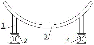
[0025] Before the penstock is transported, according to the general setting-out method, stake out the installation center line and the installation elevation control datum point. Then as attached figure 1 As shown, the transportation and construction method of the penstock in the cave mainly includes the following steps:

[0026] (1) Transportation platform, transportation track laying and traction system layout:

[0027] At the outlet of the water diversion...


PUM


Abstract

The invention discloses a transportation construction method for an in-tunnel pressure steel tube, and aims to provide a transportation construction method, capable of improving transportation efficiency, for the in-tunnel pressure steel tube. The transportation construction method comprises the following steps: (1) laying a transportation platform and a transportation rail and arranging a traction system; (3) mounting steel supporting legs and brake shoes; and (3) lifting and transporting the pressure steel tube. According to the transportation construction method, the transportation platform and the transportation rail are laid, the steel supporting legs and the brake shoes are mounted in the pressure steel tube, so that under action of traction force, the pressure steel tube slides on a rail with lubricating oil, and is transported to a to-be-mounted position. The transportation construction method solves the problems that large lifting machinery cannot be lifted in a tunnel and a transport vehicle cannot be used for transporting in the tunnel, so that the safety risks are reduced.

Description

technical field [0001] The invention relates to the technical field of hydropower station construction, in particular to a method for transporting and constructing penstock steel pipes in a cave. Background technique [0002] The water diversion system of the underground powerhouse of large, medium and small hydropower stations generally adopts a steel-lined structure. The construction passage is narrow and the steel lining itself is large in size and weight. General hoisting machinery and transportation machinery in the cave cannot be used for construction, and the construction period is long. [0003] With the existing construction method, before the excavation and support of the civil penstock hole, a large number of deep and strong anchor hooks must be specially arranged above the hole for lifting and position adjustment of the penstock during transportation. After completion, it will take a lot of labor and construction time to carry out the pull-out test of the anchor ...

Claims


Application Information

Patent Timeline
IPC IPC(8): E02B9/00E02B9/06
CPCE02B9/00E02B9/06Y02E10/20
Inventor 王建利李凤伦桑鹏
Owner SINOHYDRO BUREAU 14 CO LTD
Learn More