Rotor disc boss type periodic pressure wave generating device

A technology for generating devices and bosses, which is applied to engine components, blade support components, machines/engines, etc., and can solve the problems of unsatisfactory gas turbine heat exchange, cooling effect, large pressure fluctuation loss, and uncontrollable pressure fluctuation characteristics. , to achieve the effect of good practical effect, good adaptability and wide range of engineering applications

Inactive Publication Date: 2016-09-07
NORTHWESTERN POLYTECHNICAL UNIV
View PDF4 Cites 4 Cited by
  • Summary
  • Abstract
  • Description
  • Claims
  • Application Information

AI Technical Summary

Problems solved by technology

[0005] However, most of the pressure fluctuation air supply researched at home and abroad at present comes from the fluctuating air flow generated by the compressor. On the one hand, after the fluctuating air flow of the compressor bypasses the combustion ch

Method used


Image

  • Rotor disc boss type periodic pressure wave generating device
  • Rotor disc boss type periodic pressure wave generating device
  • Rotor disc boss type periodic pressure wave generating device

Examples


Embodiment 1

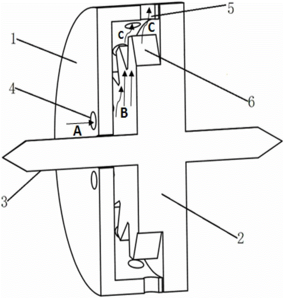
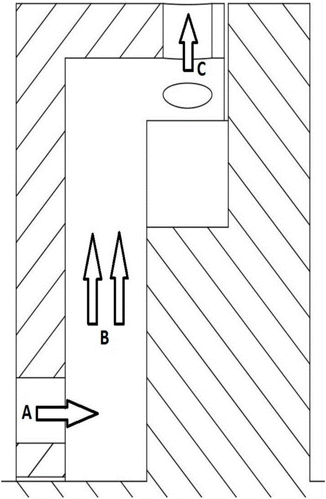
[0030]In this embodiment, the diameter of the stator plate of the boss-type periodic pressure wave generating device of the rotor is 490 mm, and the axial width is 130 mm; wherein, the distance between the center of the air inlet hole and the center of the axis is 50 mm, and the diameter of the air inlet hole is 25 mm. In the example, there are 6 air inlet holes distributed evenly in the circumferential direction, the length of the air inlet holes is 30mm; the length of the air outlet holes is 25mm, and the diameter is 5mm; in this embodiment, there are 16 air outlet holes uniformly distributed in the circumferential direction on the side wall of the stator disc. In the rotor disk, the diameter of the rotating shaft is 52mm, the diameter of the protruding part of the rotor disk is 285mm, and the width is 50mm; the diameter of the end surface of the rotor disk is 490mm, and the axial width is 30mm. Among them, the bottom surface of the boss is a curved rectangle, the arc angle θ...

Embodiment 2

[0033] In this embodiment, the diameter of the stator plate of the boss-type periodic pressure wave generating device of the rotor is 490 mm, and the axial width is 130 mm; wherein, the distance between the center of the air inlet hole and the center of the axis is 50 mm, and the diameter of the air inlet hole is 25 mm. In the example, there are 8 air inlet holes on the stator plate and they are uniformly distributed in the circumferential direction. The length of the air inlet holes is 30mm; the length of the air outlet holes is 15mm and the diameter is 10mm; indivual. In the rotor disk, the diameter of the rotating shaft is 52mm, the diameter of the protruding part of the rotor disk is 285mm, and the width is 50mm; the diameter of the end surface of the rotor disk is 490mm, and the axial width is 30mm. Among them, the bottom surface of the boss is a curved rectangle, the arc angle θ is 20°, and the arc length L in the size of the bottom surface is 1 is 49.7mm, and the dista...


PUM


Abstract

The invention discloses a rotor disc boss type periodic pressure wave generating device which is composed of a stator disc and a rotor disc. The stator disc is of a concave disc structure. A plurality of air intake holes which are the same are distributed in the end wall of the stator disc at equal intervals in the circumferential direction of a center axis hole. A plurality of air exhaust holes which are the same are formed in the circumferential side wall of the stator disc. The stator disc is installed on a rotary shaft. The rotor disc and the rotary shaft are of an integrated structure. One end face of the rotor disc is a plane, and a plurality of bosses are evenly distributed on the protruding portion of the other end face of the rotor disc in the circumferential direction. The bosses on the rotor disc correspond to air outlet holes in the stator disc in position. A cooling airflow input and output channel is formed between the rotor disc and the stator disc. Stable-pressure airflow flowing in via the air inlet holes is converted into airflow with pressure showing pressure fluctuation features with time, a periodically regular change is shown, and the airflow with the periodic pressure fluctuation features has the high heat transfer rate and good airflow heat exchange effect. The pressure wave generating device adapts to the complex working environment of high-temperature components, and is good in practical effect and wide in application range.

Description

technical field [0001] The invention relates to the cooling technology of turbine blades, in particular to a rotor piece boss type periodic pressure wave generating device. technical background [0002] Gas turbine or aeroengine is an important power device, which is widely used in various fields of power generation, ship propulsion, and aircraft propulsion. Turbine is one of the important parts of gas turbine or aero-engine, and increasing the inlet temperature of the turbine is an effective measure to increase the output power and working efficiency of gas turbine or aero-engine. At present, the inlet temperature of the turbine has reached about 2000K, far exceeding the temperature resistance limit of the material for manufacturing turbine blades. Therefore, cooling technology must be adopted for the turbine blades to ensure the reliability and stability of the turbine. The main measure is to extract air from the compressor The air cools the turbine blades. Advanced cool...

Claims


Application Information

Patent Timeline
IPC IPC(8): F01D5/18
CPCF01D5/186
Inventor 朱惠人钱鑫魏建生
Owner NORTHWESTERN POLYTECHNICAL UNIV
Why Eureka
Try Eureka