Air conditioner device with module heat exchange component and control method thereof

A technology of an air-conditioning device and a control method, which is applied to heating methods, air-conditioning systems, refrigerators, etc., can solve the problems of high cost, small adjustable range, large flow rate, etc., and achieve the effect of increasing refrigerant flow rate

Inactive Publication Date: 2016-09-07
GREE ELECTRIC APPLIANCES INC
View PDF11 Cites 15 Cited by
  • Summary
  • Abstract
  • Description
  • Claims
  • Application Information

AI Technical Summary

Problems solved by technology

There are few electronic expansion valves with a cooling capacity above 45KW, and the cost is relatively high, which is not conducive to the promotion of large cooling capacity units
However, the refrigerant flow rate of the general cooling mode system is larger than that of the heating mode system. When the large-flow electronic expansion valve meets the cooling demand, the flow rate is too large or the adjustable range is small during heating.

Method used


Image

  • Air conditioner device with module heat exchange component and control method thereof
  • Air conditioner device with module heat exchange component and control method thereof

Examples


Embodiment 1

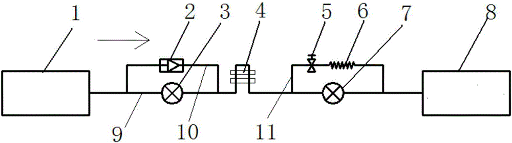
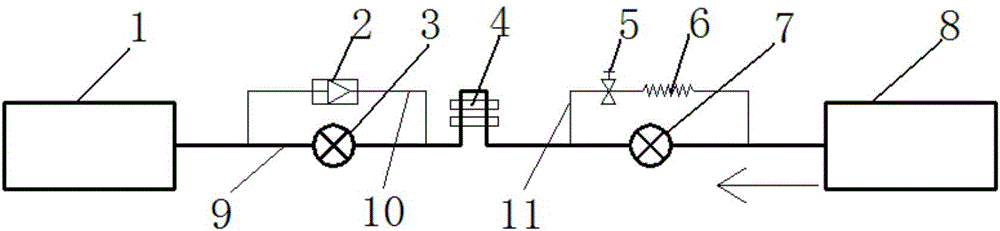
[0044] Such as figure 1 , 2 As shown, the air conditioner of the present invention has a first electronic expansion valve 3, a module heat dissipation component 4, and a second electronic expansion valve 7 arranged sequentially in the main refrigerant pipeline 9. According to different cooling or heating modes, the refrigerant flows in the The flow direction in the main refrigerant pipeline is different, and there is also a control device (not shown in the figure), which controls the first and second electronic expansion valves to play a throttling role according to the obtained signal, so that the refrigerant always exchanges heat from the module Component flow to the electronic expansion valve, which is throttling. exist figure 1 In cooling mode, the opening degree of the second electronic expansion valve 7 is adjusted by the control device according to the system load for throttling, and the first electronic expansion valve 3 is opened to the maximum opening degree withou...

Embodiment 2

[0050] As an improvement of the previous embodiment, as shown in the figure, refrigerant branch pipelines are arranged in parallel at both ends of the first and second electronic expansion valves. Through this parallel branch, the technical bottleneck of using small-flow electronic expansion valves in large cooling units has been successfully solved.

Embodiment 3

[0052] As an improvement of the previous embodiment, as shown in the figure, a one-way valve 2 is connected in series on the branch pipeline connected in parallel with the first electronic expansion valve 3 . The one-way conduction of the one-way valve is used in the parallel branch circuit, which simply and effectively solves the self-regulation of different cooling capacity requirements under the two working modes of the air conditioner.

[0053] Of course, the one-way valve 2 can also be replaced by a solenoid valve, and its on-off is controlled by the control device according to the flow direction of the refrigerant, so that the effect of the one-way valve can also be achieved.


PUM


Abstract

The invention provides an air conditioner device with a module heat exchange component and a control method thereof, and relates to the technical field of refrigeration. According to the mainly adopted technical scheme, the air conditioner device with the module heat exchange component comprises an outdoor heat exchanger (1), an indoor heat exchanger (8) and the module heat exchange component (4) which is arranged between the outdoor heat exchanger (1) and the indoor heat exchanger (8), is not provided with a compressor and is located on a main refrigerant pipeline (9). A first throttling component (3) is arranged in the position, located between the module heat exchange component (4) and the outdoor heat exchanger (1), of the main refrigerant pipeline (9). A second throttling component (7) is further arranged in the position, located between the module heat exchange component (4) and the indoor heat exchanger (8), of the main refrigerant pipeline (9). The air conditioner device with the module heat exchange component is mainly used for effective heat dissipation of an air conditioner variable frequency driving controller, can be applied to a refrigeration mode and a heating mode and can avoid the situation that the controller is damaged due to condensation and the like.

Description

technical field [0001] The invention relates to the technical field of refrigeration, in particular to an air conditioner with modular heat exchange components and a control method thereof. Background technique [0002] Inverter air conditioners are becoming popular in the market. Full DC inverter air conditioners require a dedicated drive controller to drive the compressor or motor. When the compressor or motor is running, the module of the drive controller will generate heat. If this part of the heat cannot be If it is dissipated in time, the temperature of the module will continue to rise, resulting in damage to the module. [0003] At present, the drive modules of inverter air conditioners mostly use air cooling for heat dissipation. Due to the limited heat dissipation efficiency, especially in T3 high-temperature climate conditions, the heat dissipation effect is even worse, causing the drive modules to work at high temperatures for a long time, which has a great impact...

Claims


Application Information

Patent Timeline
Patent Type & Authority Applications(China)
IPC IPC(8): F24F1/24F24F1/32F25B41/04F25B41/06F25B41/20F25B41/31
CPCF24F1/24F24F1/32F25B41/20F25B41/31Y02B30/70
Inventor 李志强
Owner GREE ELECTRIC APPLIANCES INC
Why Eureka
Try Eureka