Measuring method of motion parameter of airborne synthetic aperture radar based on position and orientation system

A measurement method, technology of motion parameters, applied in the field of aerial remote sensing

Active Publication Date: 2016-09-07
BEIHANG UNIV
View PDF3 Cites 3 Cited by
  • Summary
  • Abstract
  • Description
  • Claims
  • Application Information

AI Technical Summary

Problems solved by technology

The invention has the characteristics of high calculation accuracy and easy implementation, solves the problem of airborne SAR motion parameter measurement when there is a dynamic lever arm between the IMU measurement center and the SAR antenna phase center in the airborne SAR imaging process, and can improve the performance of synthetic aperture radar. The measurement accuracy of phase center position, velocity and attitude, thus improving the imaging accuracy of SAR antenna

Method used


Image

  • Measuring method of motion parameter of airborne synthetic aperture radar based on position and orientation system
  • Measuring method of motion parameter of airborne synthetic aperture radar based on position and orientation system
  • Measuring method of motion parameter of airborne synthetic aperture radar based on position and orientation system

Examples


Embodiment Construction

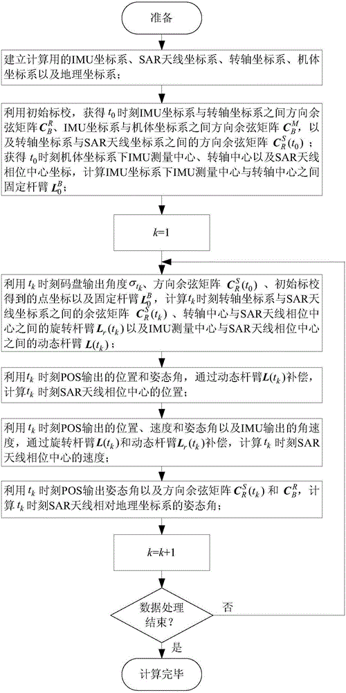
[0077] Such as figure 1 Shown, concrete implementation of the present invention comprises the following steps:

[0078] 1. Establishment of the coordinate system

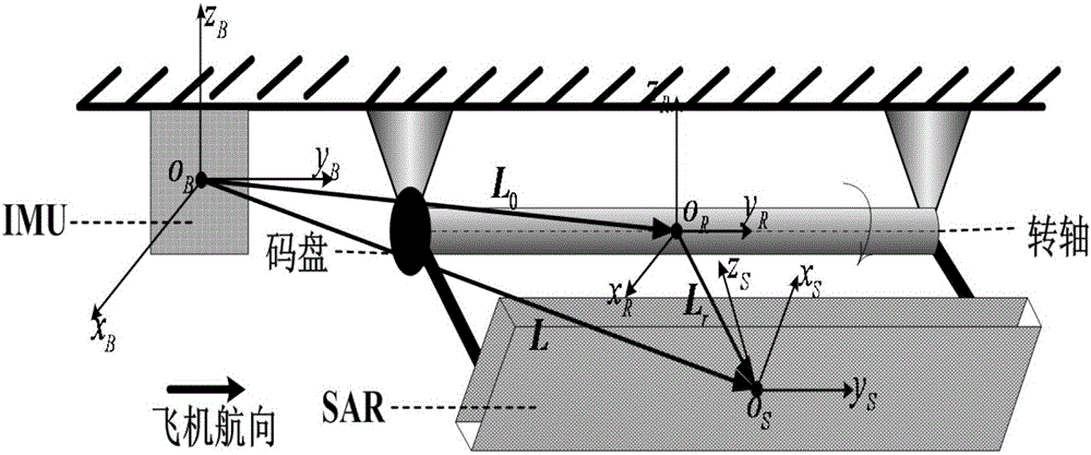
[0079] Establish the IMU coordinate system, SAR antenna coordinate system, rotating axis coordinate system, body coordinate system and geographic coordinate system, as shown in the attached figure 2 As shown, the specific coordinate system is defined as follows:

[0080] (1) IMU coordinate system O B x B the y B z B : The IMU measurement center is the origin O B , O B x B Parallel to the transverse axis of the IMU pointing to the right side of the aircraft, O B the y B The axis is parallel to the longitudinal axis of the IMU and points to the aircraft heading, O B z B The axis points vertically upwards and forms a right-handed Cartesian coordinate system with the other two axes;

[0081] (2) SAR antenna coordinate system O S x S the y S z S : The phase center of the SAR antenna array is the origin ...


PUM


Abstract

The invention relates to a measuring method of motion parameter of airborne synthetic aperture radar based on a position and orientation system. The method includes obtaining the relative position and orientation relationships between an IMU at initial moment and an indexing mechanism, the indexing mechanism and an SAR antenna by using a laser total station calibration, calculating the dynamic lever-arm between IMU measurement center and SAR antenna phase center in the IMU coordinate system and the direction-cosine matrix between the spindle coordinate system and the SAR antenna coordinate system by using the turning angle output by a coded disc, and calculating the position, speed and orientation information of the SAR antenna phase center by means of dynamic lever-arm compensation by using the position, speed and orientation output by POS, and the angular speed output by IMU. The method has high calculating accuracy, is easy to realize, and can improve the measurement accuracy of the position, speed and orientation of the SAR antenna phase center, furthermore the radar imaging accuracy is improved.

Description

technical field [0001] The invention relates to an airborne synthetic aperture radar (Synthetic Aperture Radar, SAR) motion parameter calculation method based on a position and orientation measurement system (Position and Orientation System, POS), and belongs to the field of aviation remote sensing. Background technique [0002] Airborne synthetic aperture radar is an airborne fine imaging technology for ground targets. It has important uses in the fields of land surveying and mapping, geological exploration, and agricultural monitoring. It also has important military uses in military reconnaissance and other fields. SAR imaging essentially requires that the motion state of the antenna phase center is a uniform linear motion, but for airborne SAR, the atmospheric disturbances suffered by the carrier aircraft and the movement of the SAR antenna relative to the carrier aircraft will cause the antenna phase center to deviate from the ideal state of motion. The resulting motion ...

Claims


Application Information

Patent Timeline
Patent Type & Authority Applications(China)
IPC IPC(8): G01C21/16
CPCG01C21/16
Inventor 房建成卢兆兴宫晓琳刘刚曹全刘占超张帅
Owner BEIHANG UNIV
Why Eureka
Try Eureka