Indoor available comprehensive tubing string mechanics experiment platform

A technique of pipe string mechanics and experimental platform, applied in the direction of using stable torsion to test material strength, using stable bending force to test material strength, and using stable tension/pressure to test material strength, etc. It can improve the stability of the whole machine, reduce the cost and scale, and simplify the processing and installation.

Active Publication Date: 2016-09-07
NORTHEAST GASOLINEEUM UNIV
View PDF9 Cites 11 Cited by
  • Summary
  • Abstract
  • Description
  • Claims
  • Application Information

AI Technical Summary

Problems solved by technology

Therefore, the tubing will often buckle in the casing, and the buckling deformation of the tubing will cause the axial positions of the packers, water distributors and other components installed on the tubing to move in series, resulting in injection-production cascading and even downhole tool failure.
At present, the oilfield site can use the magnetic positioning method to measure the position series movement of each component before and after the pipe string works, but the magnetic positioning method cannot predict the position series movement of each component in the working state before the pipe string is run in.
[0003] In order to study the deformation of the pipe string under complex working conditions downhole, many foreign scholars (such as Lubinski, Hammerlindl etc.) based on theoretical basis respectively, established a series of research theories and auxiliary experimental methods of pipe string mechanics under different conditions, but these research theories generally ignore a certain force or boundary condition of the pipe string, and need to be given It is only approximately true when the assumption is true, and the deformation of the pipe string under actual working conditions cannot be comprehensively and accurately given; moreover, due to the complexity of the pipe string buckling phenomenon itself, it is usually difficult to analyze in many auxiliary experiments such as end However, the independent influence of internal boundary constraints, pipe string

Method used


Image

  • Indoor available comprehensive tubing string mechanics experiment platform
  • Indoor available comprehensive tubing string mechanics experiment platform
  • Indoor available comprehensive tubing string mechanics experiment platform

Examples


Embodiment Construction

[0039] Below in conjunction with accompanying drawing, the present invention will be further described:

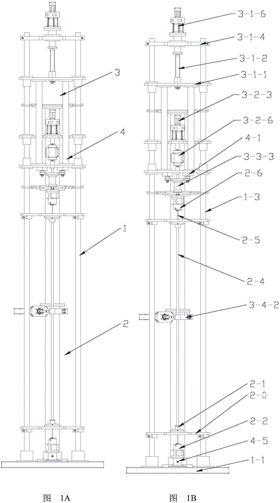
[0040] Depend on Figure 1A Shown: a comprehensive pipe mechanics experiment platform available indoors, including frame 1, specimen and its sealing system 2, loading and transmission system 3 and control system 4.

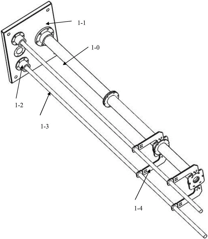
[0041] Depend on figure 2 As shown: the frame 1 includes the main stress column 1-0, two auxiliary guide columns 1-3 and the lower platform 1-1, the main force column 1-0 and the two auxiliary guide columns 1-3 pass through The torsion support frame 1-4 is connected to form a tripod structure, in which the main force column 1-0 adopts a three-stage structure, and is fixed by straight positioning and flange connection. The main force column 1-0 and the lower platform 1- 1 adopts straight mouth positioning and flange connection, and the auxiliary guide column 1-3 is fixedly connected to the lower table 1-1 by using the expansion sleeve 1-2, so the whole machi...


PUM


Abstract

The invention discloses an indoor available comprehensive tubing string mechanics experiment platform to solve the problem of unable accurate synchronous application of pulling, pressing, bending, twisting and other loads of present indoor experiment devices. The platform integrates loading and test mechanisms of pulling, pressing, bending, twisting and other different loads, and eliminates mutual influences of pulling and twisting combination load in a bearing isolation manner, and a test terminal collects and processes a pulling and twisting load signal in a double-sensor merging output mode. The platform can realize synchronous loading and testing of pulling, bending, twisting and other loads, and allows the real deformation of an oilfield tubing string under a given load condition to be obtained through scaling all parts of the oilfield tubing string in the practical use process.

Description

technical field [0001] The invention relates to an experimental research device applied in the technical field of pipe string mechanical behavior research. Background technique [0002] The length-to-diameter ratio of the oilfield tubing string is extremely large, the annular gap between the oil casing and the casing is extremely small, and the downhole load is also extremely complicated. The deformation of the tubing string in the downhole is often a combination of contact and friction boundaries, and is affected by the The result of a combination of tensile (or compressive) and bending loads and torques. Therefore, the tubing will often buckle in the casing, and the buckling deformation of the tubing will cause the axial position of the packer, water distributor and other components installed on the tubing to move in series, resulting in the injection-production cascade and even the failure of downhole tools. At present, the oilfield site can use the magnetic positioning ...

Claims


Application Information

Patent Timeline
IPC IPC(8): G01N3/08G01N3/20G01N3/22
CPCG01N3/08G01N3/20G01N3/22G01N2203/0017G01N2203/0019G01N2203/0021G01N2203/0023
Inventor 王尊策温后珍曹梦雨李森徐艳闫月娟
Owner NORTHEAST GASOLINEEUM UNIV
Why Eureka
Try Eureka