Flexible fabric switch

A flexible fabric and switch technology, applied in the field of wearable electronic devices, can solve the problems of poor shear resistance, limited life, short life, etc., achieve improved stability and fatigue resistance, adjustable conduction pressure, and simple structure Effect

Active Publication Date: 2016-09-07
ZHUHAI ADVANPRO TECH
View PDF5 Cites 17 Cited by
  • Summary
  • Abstract
  • Description
  • Claims
  • Application Information

AI Technical Summary

Problems solved by technology

This structure has poor shear resistance and will fail once it is dislocated; and its life is

Method used


Image

  • Flexible fabric switch
  • Flexible fabric switch
  • Flexible fabric switch

Examples


preparation example Construction

[0028] The preparation method of the above-mentioned flexible fabric switch comprises the following steps:

[0029] a) compounding the elastic isolation layer and the adhesive layer;

[0030] b) cutting or punching through holes with a knife on the composite elastic isolation layer;

[0031] c) the upper conductive layer and the lower conductive layer are respectively connected to conductive wires;

[0032] d) Composite the elastic isolation layer with the upper conductive layer and the lower conductive layer respectively through the adhesive layer.

Embodiment 1

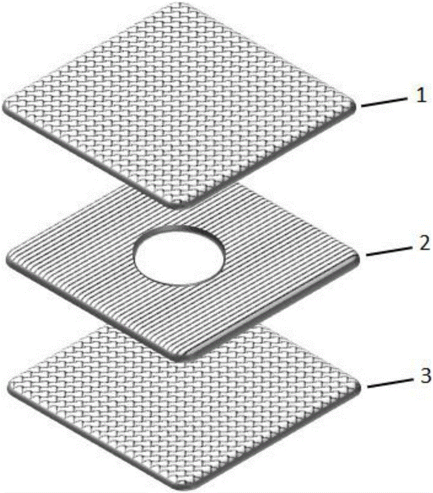
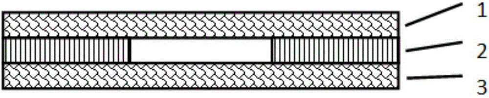
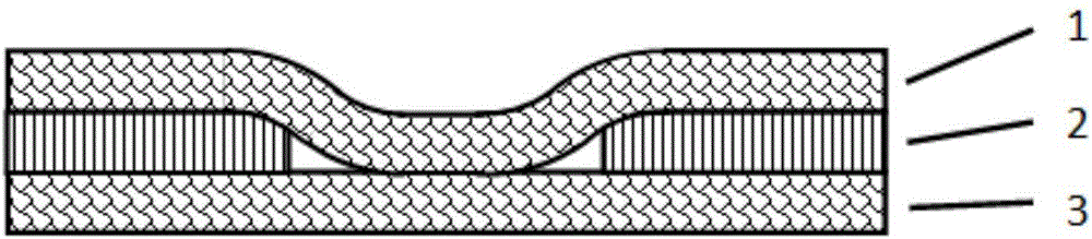
[0034] A flexible fabric switch comprises an upper conductive layer, a lower conductive layer, and an elastic isolation layer arranged between the upper conductive layer and the lower conductive layer, and is compounded by an adhesive layer. The upper conductive layer and the lower conductive layer are made of silver-plated fiber conductive fabric; the elastic isolation layer is made of warp-knitted elastic knitted fabric woven from polyurethane filaments, and a single circular through hole is cut in the middle of the elastic isolation layer; the adhesive layer is selected from thermal insulation. Melted TPU film.

[0035] The preparation method of the flexible fabric switch in this embodiment comprises the following steps:

[0036] a) The elastic knitted fabric and the hot-melt TPU film are combined and bonded by hot pressing, and the middle is elastic knitted

[0037] Cloth, with hot-melt TPU film on the top and bottom, made of elastic isolation layer;

[0038] b) cutting ...

Embodiment 2

[0042] A flexible fabric switch comprises an upper conductive layer, a lower conductive layer, and an elastic isolation layer arranged between the upper conductive layer and the lower conductive layer, and is compounded by an adhesive layer. Copper-plated fiber conductive fabric is used for the upper conductive layer and the lower conductive layer; the elastic isolation layer is made of silica gel, and three circular through holes are cut in the middle of the elastic isolation layer; acrylic adhesive is selected for the adhesive layer.

[0043] The preparation method of the flexible fabric switch in this embodiment comprises the following steps:

[0044] a) bonding the elastic release layer with an acrylic adhesive;

[0045] b) using a laser cutting machine to cut out three circular through holes in the composite elastic isolation layer;

[0046] c) The upper conductive layer and the lower conductive layer are respectively connected to the upper silver-plated fiber conductive...


PUM


Abstract

The invention discloses a flexible fabric switch, and belongs to the field of wearable electronic equipment. The flexible fabric switch comprises an upper conductive layer and a lower conductive layer, wherein an elastic isolation layer is arranged between the upper conductive layer and the lower conductive layer; one or more through holes are formed in the elastic isolation layer; and the upper conductive layer and the lower conductive layer are connected with conductive wires respectively. The flexible fabric switch is simple in structure; meanwhile, the upper conductive layer and the lower conductive layer can be in surface-surface contact for conduction; and in addition, the flexible fabric switch is light, thin and stable, and high in stability, fatigue resistance, bending resistance, and shearing resistance.

Description

technical field [0001] The invention relates to the field of wearable electronic devices, in particular to a flexible fabric switch applicable to smart textiles. Background technique [0002] At present, most of the switches used for switching are hard switches, and the parts for pressing are made of hard materials such as metal or plastic, so they will have a stiff touch when touched, and when used in various In different livelihood applications, especially when applied to clothing or other electronic products made of soft materials, this hard switch will produce an abrupt hard touch and gradually fail to meet people's needs. Therefore, in order to meet the demand, people have gradually developed soft-touch fabric switches, which can be applied to wearable electronic devices and smart textiles. At present, the upper and lower electrodes of these fabric switches are mostly connected through point-to-point, point-to-line or line-to-line contact. This structure has poor shea...

Claims


Application Information

Patent Timeline
IPC IPC(8): H01H13/704
CPCH01H13/704H01H2209/052H01H2209/074
Inventor 王飞饶良魁王杨勇王广峰
Owner ZHUHAI ADVANPRO TECH
Why Eureka
Try Eureka