Drop-out fuse

A technology of drop-out fuses and fuse tubes, which is applied in the direction of electrical components, circuits, emergency protection devices, etc., can solve the problems of complex assembly process and difficult production efficiency of drop-out fuses, achieve simple structure, improve production efficiency, and manufacture convenient effect

Inactive Publication Date: 2016-09-07
常德威迪电气有限责任公司
View PDF7 Cites 0 Cited by
  • Summary
  • Abstract
  • Description
  • Claims
  • Application Information

AI Technical Summary

Problems solved by technology

In detail, the connection between the rainproof cap of the existing drop-out fuse and its guide fork is a detachable connection, which can cause the assembly process of the drop-out fuse to become complicated, and it is not easy to improve production efficiency

Method used


Image

  • Drop-out fuse
  • Drop-out fuse
  • Drop-out fuse

Examples


Embodiment 1

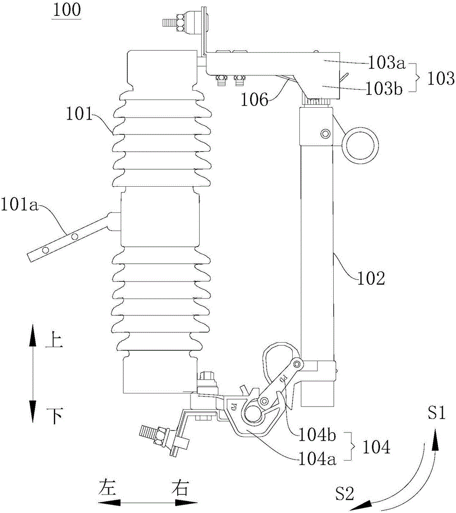
[0033] figure 1 It is a schematic structural diagram of a dropout fuse 100 according to Embodiment 1 of the present invention; figure 2 It is a structural schematic diagram of the rainproof cap 103 of the dropout fuse 10 according to Embodiment 1 of the present invention. like figure 1 and figure 2 As shown, the dropout fuse 100 includes an insulator 101 . The insulator 101 is preferably a ceramic insulator or a synthetic insulator. The insulator 101 can be installed on the utility pole or other positions to be installed through the holed sheet 101a in the middle.

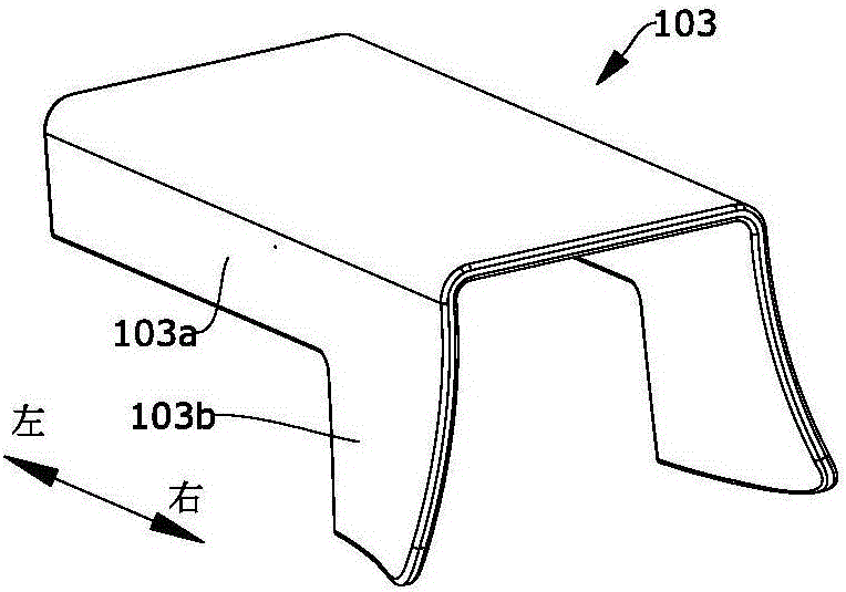
[0034] The dropout fuse 100 also includes a rainproof cap 103 . The rainproof cap 103 has an integrated structure, and has an inverted U-shaped portion 103a and two sheet guides 103b, wherein each sheet-shaped guide 103b is connected to the corresponding lower edge of the right end of the inverted U-shaped portion 103a respectively ( That is, one sheet-shaped guide portion 103b is connected to one side lowe...

Embodiment 2

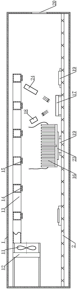
[0042] image 3 It is the detection system and dust cleaning system of the drop-out fuse according to the second embodiment of the present invention; image 3 It is a circuit diagram of the detection system of the drop-out fuse according to the second embodiment of the present invention; Figure 4 is a partial view of the self-adaptive air outlet in Embodiment 2; Figure 5 It is a partial view of the heat sink of the component in the second embodiment; among the figures, the meanings indicated by each reference mark are as follows; 1, the housing; 2, the PCB circuit board; 11, cleaning the air intake device; 12, the filter device; 13, Cleaning pipeline; 14. Self-adaptive air outlet; 15. Bimetal sheet; 16. Single heat sink; 17. Mirror surface; 18. Photosensitive switch; 19. Circuit components; 20. Air exhaust port; ; 24. Laser generator. The second embodiment is to increase the detection system and the dust cleaning system on the basis of the first embodiment.

[0043] The ...

Embodiment 3

[0065] Image 6 It is a structural schematic diagram of the heat sink in Embodiment 3 of the present invention; in the figure, the meanings indicated by the reference signs that have appeared in the drawings used in Embodiment 2 follow the meanings in the drawings of Embodiment 2, and the newly appearing reference symbols The meanings expressed are as follows;

[0066]The difference between this embodiment and embodiment two is:

[0067] The individual heat sinks 16 are all arranged on an insulating and heat-conducting body 23 , and each individual heat sink 16 is divided along a circle.

[0068] The insulated heat conductor 23 can be an insulating layer attached to a metal material, so that the individual heat sinks 16 are insulated from each other without significantly reducing the thermal conductivity, so that the individual heat sinks 16 of the heat sink form a capacitor.


PUM


Abstract

The invention relates to a drop-out fuse. The drop-out fuse comprises an insulator, a rain hat, a dropping device and a fusion tube, wherein the rain hat is provided with an inverted U-shaped part and two sheet-shaped guiding parts, and is of an integral structure; a conductive component is arranged in the inverted U-shaped part; the dropping device comprises a first conductive base and a second conductive base; the first conductive base is connected with a lower end of the insulator; and the fuse tube is connected with the second conductive base, and hung in a hooking groove of the first conductive base through a hanging pole of the second conductive base in order that the fusion tube can rotate relative to the insulator. When the fusion tube rotates upwards relative to the insulator, an upper end of the fusion tube is guided into the rain hat under the guiding actions of the sheet-shaped guiding parts, and clamped with a clamping groove. In the rain hat of the drop-out fuse, a conventional rain hat and a guiding fork are combined, so that the rain hat of the drop-out fuse has a guiding function; an assembly process can be simplified; and the production efficiency can be increased easily.

Description

technical field [0001] The invention relates to a dropout fuse. Background technique [0002] The technical idea of ​​the dropout fuse is mainly derived from foreign countries, but there are problems in its domestic application. In detail, the connection between the rainproof cap of the existing drop-out fuse and its guide fork is detachable, which makes the assembly process of the drop-out fuse complicated and difficult to improve production efficiency. Contents of the invention [0003] Based on the above problems, the object of the present invention is to provide a drop-out fuse. The rainproof cap used in it combines the traditional rainproof cap and the guide fork into one, so as to ensure that the rainproof cap of the drop-out fuse has a guiding function. And the assembly process can also be simplified, so that the production efficiency can be easily improved. [0004] The present invention provides a drop-out fuse, which comprises: an insulator; a rainproof cap wit...

Claims


Application Information

Patent Timeline
Patent Type & Authority Applications(China)
IPC IPC(8): H01H85/54
CPCH01H85/54
Inventor 高建民高碧寒
Owner 常德威迪电气有限责任公司
Why Eureka
Try Eureka