Pneumatic quick-changing clamp

A technology for quick-change clamps and cylinders, applied in the directions of clamping, manufacturing tools, supports, etc., can solve problems such as low efficiency and difficult operation, and achieve the effects of convenient processing, increased load, and simple structure

Pending Publication Date: 2020-06-02
CHONGQING CHANGZHENG HEAVY IND
View PDF0 Cites 3 Cited by
  • Summary
  • Abstract
  • Description
  • Claims
  • Application Information

AI Technical Summary

Problems solved by technology

[0002] When the workpiece needs to change the processing orientation and operating machine po

Method used


Image

  • Pneumatic quick-changing clamp
  • Pneumatic quick-changing clamp
  • Pneumatic quick-changing clamp

Examples


Embodiment Construction

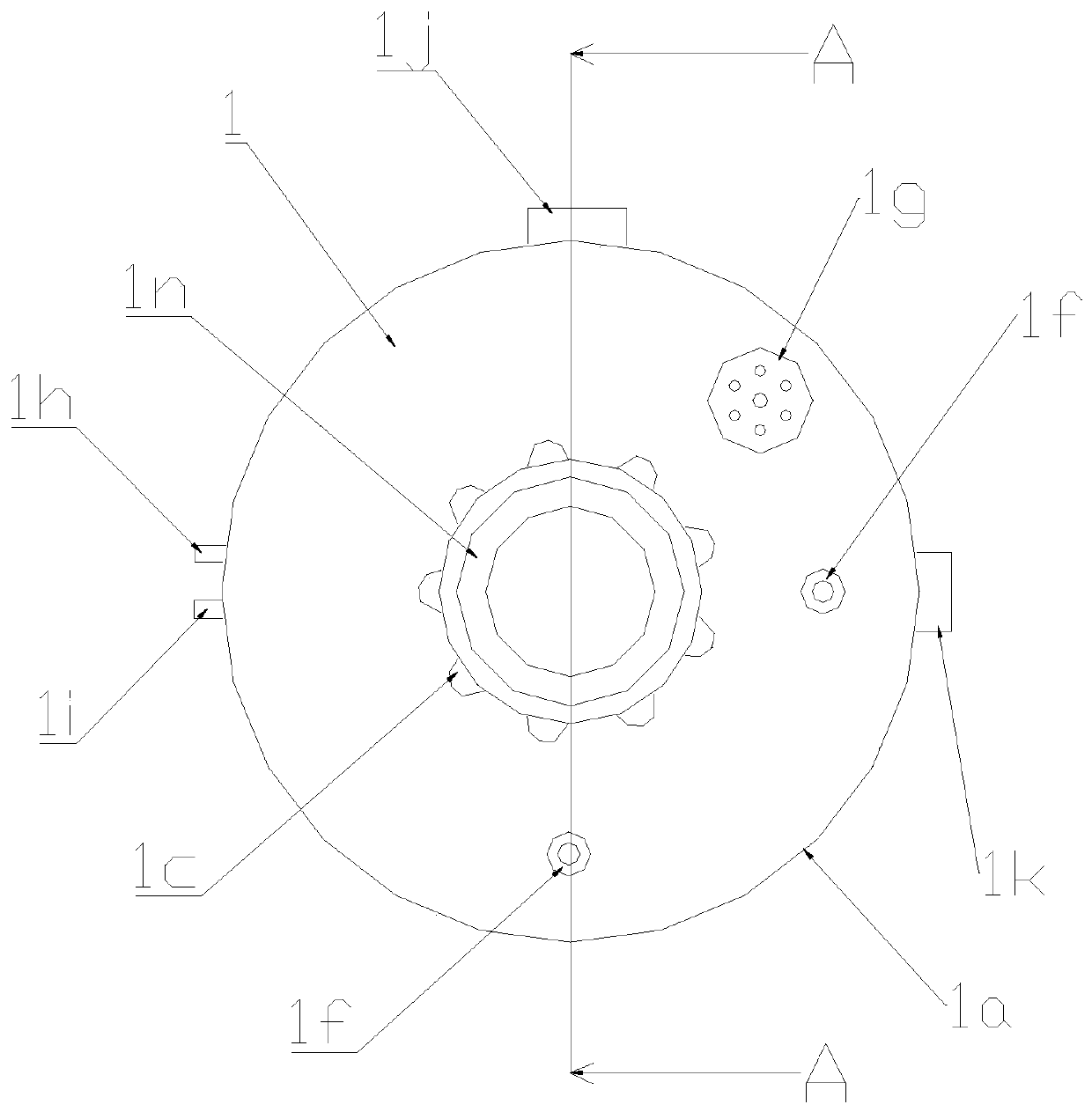
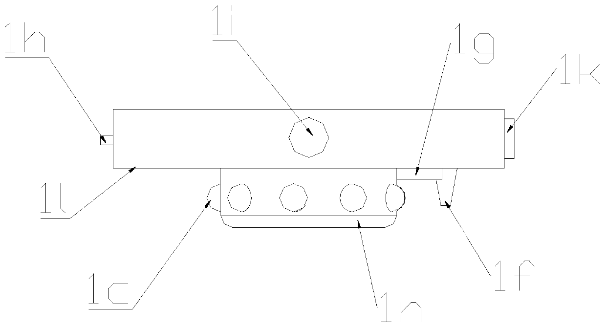
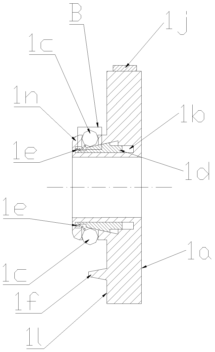
[0027] It should be noted that, unless otherwise specified, all technical and scientific terms used in this application have the same meaning as commonly understood by those of ordinary skill in the art to which this application belongs.

[0028] In order to enable those skilled in the art to better understand the solution of the present application, the technical solution in the embodiment of the application will be clearly and completely described below in conjunction with the accompanying drawings in the embodiment of the application. Obviously, the described embodiment is only It is an embodiment of a part of the application, but not all of the embodiments. Based on the embodiments in this application, all other embodiments obtained by persons of ordinary skill in the art without creative efforts shall fall within the scope of protection of this application.

[0029] It should be noted that the terms "first" and "second" in the description and claims of the present applica...


PUM


Abstract

The invention discloses a pneumatic quick-changing clamp which comprises a driving part and a reloading part, wherein the driving part and the reloading part form pneumatic clamping connection througha plurality of balls distributed on the circumference of the driving part and matching holes in the reloading part; and an annular arc shaped groove for receiving the balls is formed in the walls ofthe matching holes. With adoption of the pneumatic quick-changing clamp, the annular arc shaped groove for receiving the balls is formed in the walls of the matching holes, when the pressure force issufficient, frictional resistance generated by positive pressure exists between the balls and the reloading part, and a radial overlapped part bears the axial force formed by the gravity of a workpiece and the reloading part; and the pneumatic quick-changing clamp can remarkably increase the load of the quick-changing clamp, can meet the using requirements of large and medium-sized components andis simple in structure and convenient to machine.

Description

technical field [0001] The invention relates to a clamp, in particular to a pneumatic quick-change clamp. Background technique [0002] When the workpiece needs to change the processing orientation and operating machine position, the manual operation and changing the station are inefficient and difficult to operate. In order to solve this problem, an automatic changeover method in which robots are used to replace manual labor is introduced, which realizes quick changeover through the pneumatic quick-change structure between the active part fixedly connected on the robot and the changeover part fixedly connected to the workpiece, thus The workpiece is driven by the robot to clamp the product on the processing equipment, or to achieve grinding, welding and other processing purposes with the robot's set motion trajectory; and use the changing part to connect with different workpieces to achieve the purpose of workpiece replacement. The existing pneumatic quick change structure...

Claims


Application Information

Patent Timeline
IPC IPC(8): B23Q3/08
CPCB23Q3/08
Inventor 李沛海甘能
Owner CHONGQING CHANGZHENG HEAVY IND
Why Eureka
Try Eureka