Electric current sensor

A technology of current sensor and current path, applied in the direction of measuring device, voltage/current isolation, instrument, etc., can solve the problem of inability to detect current correctly, achieve the effect of suppressing malfunction and reducing manufacturing cost

Active Publication Date: 2016-09-14
TAMURA KK
View PDF7 Cites 4 Cited by
  • Summary
  • Abstract
  • Description
  • Claims
  • Application Information

AI Technical Summary

Problems solved by technology

[0004] However, even if a coreless current sensor device that does not use a magnetic core is simply used for the current detection of the bus line, the magnetic flux generated from other bus lines (for example, adjacent bus lines of other phases) and the like will be captured. are affected by it, so the current cannot be sensed correctly

Method used


Image

  • Electric current sensor
  • Electric current sensor
  • Electric current sensor

Examples


no. 1 Embodiment approach

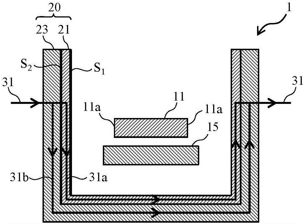
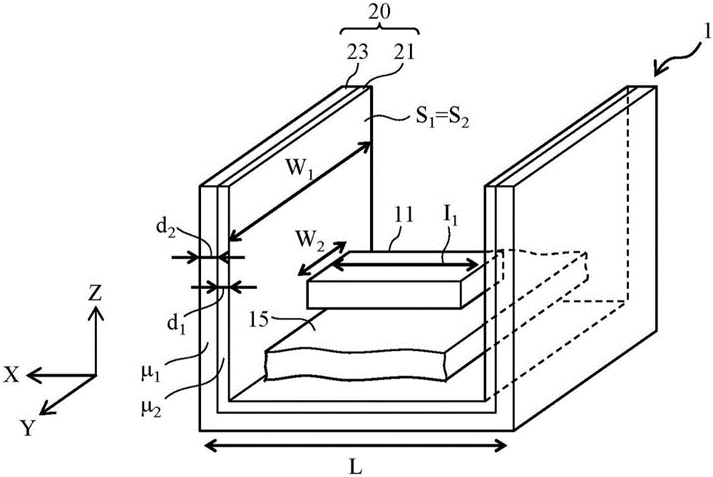
[0044] FIG. 2( a ) is a cross-sectional view showing an example of the configuration of the current sensor device according to the first embodiment of the present invention. Fig. 2(b) is a perspective view of the current sensor device shown in Fig. 2(a). Hereinafter, description will be made with reference to the x, y, and z axes defined in each figure.

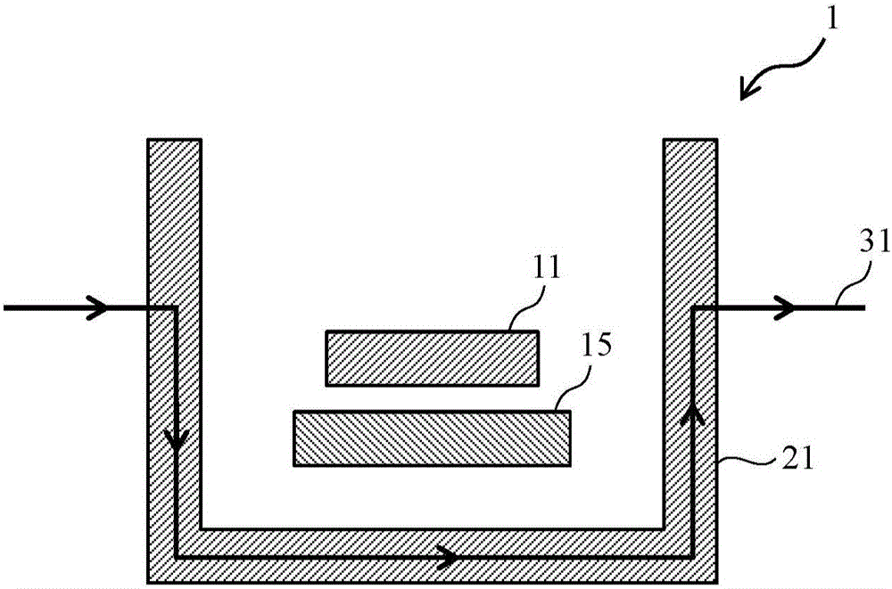
[0045] As shown in FIG. 2(a) and FIG. 2(b), the current sensor device 1 of this embodiment includes, for example, a magnetic detection element (hereinafter also referred to as IC) 11 such as a Hall element. The current path extending in the y-axis direction, that is, the bus 15 . As the magnetic detection element 11 , for example, any one of a Hall element, a magnetoresistive element, and a Hall IC (IC: Integrated Circuit) combining a Hall element and an amplifier circuit can be used. As the magnetoresistance element, an anisotropic magnetoresistance element AMR, a gigantic magnetoresistance element GMR, a tunnel magnetores...

Embodiment 1

[0056] In Figure 2(a), it is possible to have the first relative permeability μ 1 The first magnetic shielding material, for example, becomes the magnetic permeable alloy PC material, so that it has the second relative magnetic permeability μ 2 The second magnetic shielding material is, for example, ferrite. The relative magnetic permeability of the magnetic permeable alloy PC material exceeds 5000, and the relative magnetic permeability of the ferrite is about 2000. In comparison, the former is more expensive. The relative magnetic permeability of the magnetic permeable alloy PC material with a thickness of 0.1mm is tens of thousands to hundreds of thousands, and the relative magnetic permeability of the magnetic permeable alloy PB material with a thickness of 0.1mm is 10,000 to 20,000, which is about 3,000 in 0.35mm. Therefore, the layer thickness of the magnetic permeable alloy is made as thin as possible, and the correspondingly reduced magnetic shielding effect is compe...

no. 2 Embodiment approach

[0091] Next, a second embodiment of the present invention will be described. FIG. 7( a ) is a cross-sectional view showing a configuration example of the current sensor device of the present embodiment. FIG. 7( b ) is a cross-sectional view showing a current sensor device according to a modified example of FIG. 7( a ). The difference from the first embodiment is that the second magnetic shield portion 23a having the second relative magnetic permeability is formed of a composite material of a magnetic material and a non-magnetic material such as a resin material. Although the effects related to the magnetic shielding produced by this structure are the same as those of the first embodiment, there is an advantage that by using an inexpensive composite material of a magnetic material and a non-magnetic material such as a resin material, it is different from that of the first embodiment. than can increase the cost reduction effect. As shown in FIG. 7(b), the second magnetic shiel...


PUM


Abstract

The invention provides a current sensor device capable of avoiding error action of current detection caused by an external magnetic field and cutting cost. The current sensor device is magnetic core-free and is provided with a magnetic detection element detecting magnetic flux generated in a current path; and a magnetic shielding part arranged around the magnetic detecting element and shielding magnetic flux for the magnetic detection element and from the external. The magnetic shielding part is provided with a first magnetic shielding part made of a first magnetic shielding material having a first relative magnetic conducting rate and a second magnetic part made of the a second magnetic shielding material having a second magnetic conducting rate different from the first magnetic conducting rate.

Description

technical field [0001] The present invention relates to a current sensor device, and more particularly to a coreless current sensor device using a magnetic detection element. Background technique [0002] A current sensor device is generally used to measure the current of a battery power supply of an automobile or the like. As a current detection device for detecting a current flowing in a power line (power line) such as a current path (hereinafter referred to as "bus bar"), the following current detection device is known. The magnetic core that surrounds the bus in the circumferential direction collects the magnetic flux generated around it according to the current flowing in the bus, and detects the collected magnetic flux by a magnetic detection element such as a Hall element. detect current. [0003] On the other hand, there has also been proposed a coreless current sensor device that detects a current flowing through a bus by directly detecting a magnetic flux without...

Claims


Application Information

Patent Timeline
Patent Type & Authority Applications(China)
IPC IPC(8): G01R15/20
CPCG01R15/202G01R15/205
Inventor 余孔惠小林正和
Owner TAMURA KK
Why Eureka
Try Eureka