A compressor system for a rail vehicle and method for operating the compressor system with safe emergency operation

A technology for compressor systems and rail vehicles, which can be used in machine/engine, railway signal and safety, railway vehicle heating/cooling, etc., and can solve problems such as rail vehicle stop

Inactive Publication Date: 2016-09-14
KNORR BREMSE SYST FUR SCHIENENFAHRZEUGE GMBH
View PDF3 Cites 2 Cited by
  • Summary
  • Abstract
  • Description
  • Claims
  • Application Information

AI Technical Summary

Problems solved by technology

Because the compressor system supplies compressed air to the braking equipment,

Method used


Image

  • A compressor system for a rail vehicle and method for operating the compressor system with safe emergency operation
  • A compressor system for a rail vehicle and method for operating the compressor system with safe emergency operation
  • A compressor system for a rail vehicle and method for operating the compressor system with safe emergency operation

Examples


Embodiment Construction

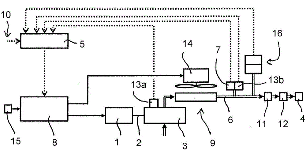
[0022] according to figure 1 , a compressor system for a rail vehicle has an electric motor 1 , which drives a compressor 3 for generating compressed air via a drive shaft 2 . The compressed air produced by the compressor 3 is conducted via a compressed air-conducting line 6 to a cooling unit 9 with a cooling fan 14 . Downstream of the cooling unit 9 , a pressure sensor 7 and a temperature sensor 13 b are arranged in the line 6 carrying compressed air. Furthermore, the line 6 carrying compressed air leads into a pre-separator 11 , after which an air treatment unit 12 is connected. Dry and particle-free compressed air is then fed into the compressed air container 4 . Furthermore, a pressure switch 16 for monitoring the pressure in the compressed air container 4 and for indirectly influencing the speed of the electric machine 1 and the cooling fan 14 is arranged in the line 6 carrying the compressed air.

[0023] The temperature sensor 13 a , the temperature sensor 13 b and t...


PUM


Abstract

The invention relates to a compressor system for a rail vehicle, comprising a compressor (3), driven by an electrical machine (1) via a drive shaft (2), for producing compressed air for at least one compressed air tank (4), wherein the electrical machine (1) can be activated at least indirectly via a control device (5) for operating the electrical machine (1) at at least one nominal speed (n) between a maximum speed (m) and a minimum speed (i), wherein furthermore at least one pressure sensor (7) for determining the pressure for the control device (5) is disposed in a compressed-air-carrying line (6) downstream of the compressor (3). According to the invention, a final control element (8) for continuously influencing the speed of the electrical machine (1) is disposed between an electrical supply (15) and the electrical machine (1), wherein the final control element (8) can be activated via the control device (5), and wherein a pressure switch (16) for monitoring the pressure in the at least one compressed air tank (4) and for influencing at least the speed of the electrical machine (1) is disposed in the compressed-air-carrying line (6) downstream of the compressor (3). Furthermore, the invention also relates to a method for controlling the compressor system according to the invention, wherein the compressor (3) is operated at a variable speed, assuming any intermediate value between the maximum speed (m) and the minimum speed (i), and wherein the pressure switch (16) monitors the pressure in the at least one compressed air tank (4) and has an indirect influence at least on the speed of the electrical machine (1).

Description

technical field [0001] The invention relates to a compressor system for a rail vehicle comprising a compressor driven by an electric motor via a drive shaft for generating compressed air for at least one compressed air container, wherein the electric motor can be controlled at least indirectly via a regulated The device is actuated to operate the electric motor at at least one setpoint speed between a maximum speed and a minimum speed, and at least one pressure sensor is provided in the compressed air line downstream of the compressor for regulating the The device determines the pressure. The invention also relates to a method for controlling a compressor system according to the invention. Background technique [0002] Compressors in rail vehicles place multiple and partly opposite demands, such as high supply power, sufficient on-time, low sound emissions, low energy consumption, small installation space and low acquisition costs and life cycle costs. Depending on the op...

Claims


Application Information

Patent Timeline
IPC IPC(8): F04B35/04F04C28/08F04B41/02F04B49/06F04B49/08F04B49/20F04D25/06F04D27/00
CPCF04B35/04F04B41/02F04B49/06F04B49/20F04B2203/0209F04B2205/05F04B49/08B61D27/00B61L25/021B61L25/025B61L2205/04
Inventor T·基普G·阿斯曼
Owner KNORR BREMSE SYST FUR SCHIENENFAHRZEUGE GMBH
Why Eureka
Try Eureka