Controllable vibration damper for motor vehicles
What is Al technical title?
Al technical title is built by PatSnap Al team. It summarizes the technical point description of the patent document.
A technology for vibration dampers and motor vehicles, which is applied in the direction of shock absorbers, liquid shock absorbers, spring/shock absorber functional characteristics, etc., and can solve the problems of high manufacturing cost, complex structure, and the inability to change only the damper, etc.
Active Publication Date: 2016-09-14
THYSSENKRUPP BILSTEIN
View PDF12 Cites 2 Cited by
Summary
Abstract
Description
Claims
Application Information
AI Technical Summary
This helps you quickly interpret patents by identifying the three key elements:
Problems solved by technology
Method used
Benefits of technology
Problems solved by technology
[0006] However, the construction of the valve sub-assemblies of these vibration dampers is in some cases very complex or in some cases requires specific parts which are very expensive to manufacture
Furthermore, it is generally not possible to selectively change only the characteristics of a single function of the damper for other application areas by merely replacing individual components
Method used
Image
Click on the blue label to locate the original text in one second.
Reading with bidirectional positioning of images and text.
Examples
Embodiment Construction
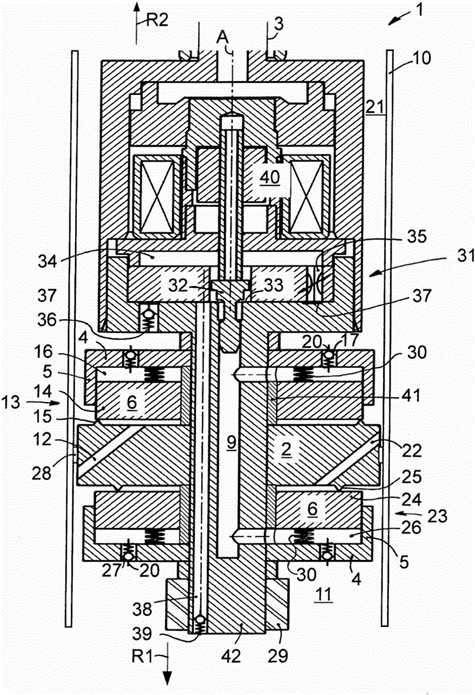
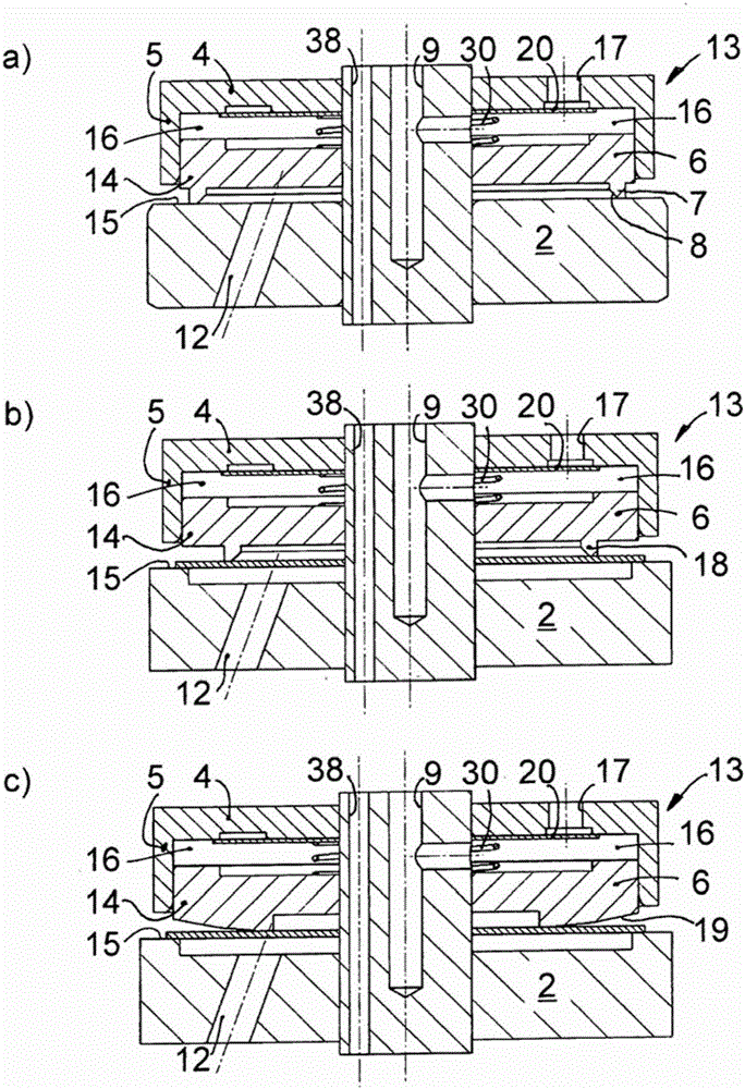
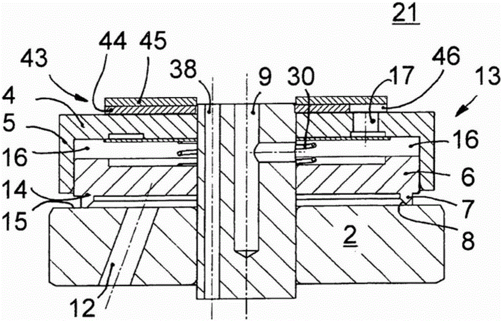
[0037] figure 1 A detailed view of the vibration damper 1 according to the first embodiment of the invention is shown in section. Unless otherwise stated, the basic construction and operation described also applies to figure 2 a to figure 2 Other implementations in c.
[0038] The vibration damper 1 comprises a cylinder tube 10 in which a piston 2 is held movable along a cylinder tube axis A. As shown in FIG. The piston 2 has an annular seal 28 on its outer periphery, so that the piston 2 divides the cylinder tube 10 into a first working space 11 and a second working space 21 in a sealed manner. The piston 2 is fastened on a fastening pin 42 which in turn is firmly connected to the piston rod 3 . When the piston rod 3 is actuated towards the first working space 11 in the first actuating direction R1, the pressure in the first working space 11 increases. The fluid present in the first working space 11 then circulates through the first fluid channel 12 in the piston 2 int...
PUM
Abstract
The invention relates to a controllable vibration damper (1), in particular for a vehicle body, comprising a cylindrical tube (10) which has a hydraulic fluid that is sealed in the cylindrical tube, a piston (2) which is axially movable within the cylindrical tube (10) along a cylindrical tube axis (A) and which divides the cylindrical tube (10) into two work chambers (11, 21), and a piston rod (3) which is oriented parallel to the cylindrical tube axis (A) and which is connected to the piston (2) at one end, multiple fluid passages (12, 22) from one work chamber (11, 21) to the other work chamber (21, 11) being provided in the piston. A first valve assembly (13) for damping the piston movement in a first actuation direction (R1) is arranged in a first fluid passage (12), and a second valve assembly (23) for damping the piston movement in a second actuation direction (R2) is arranged in a second fluid passage (22), each valve assembly (13, 23) having at least one valve disk (14, 24) which sits on a valve seat (15, 25) in a closed valve position and is at least partly removed from the valve seat (15, 25) in an open valve position. Each valve assembly (13, 23) comprises a pilot control chamber (16, 26), and a pressure in the pilot control chamber (16, 26) urges the valve disk (14, 24) into the closed valve position, the pressure in each of the pilot control chambers (16, 26) being adjustable. According to the invention, one of the pilot control chambers (16, 26) is delimited by a base (4), a cylindrical lateral wall (5) which is stationary relative to the base (4) and which is coaxial to the cylindrical tube axis (A), and a dimensionally stable cover (6) which can be moved parallel to the cylindrical tube axis (A) in a radial manner within the cylindrical lateral wall (5).
Description
technical field [0001] The invention relates to a controllable vibration damper according to the preamble of claim 1 . Background technique [0002] Such a vibration damper is known from DE 44 41 047 C1. A pressure-dependent damping valve is provided on the axially guided piston within the cylinder tube in order to allow fluid to be exchanged between the two working spaces during the expansion and compression phases. Pilot control is performed such that a controlled pressure builds up in the pilot chamber. Pilot pressure pushes the orifice valve disc toward the orifice valve's closed position. Fluid flows out of the working space through the bypass channel system into the pilot chamber, thus increasing the pressure at the pilot chamber. Pilot pressure is controlled by means of an externally adjustable pilot valve arranged in a bypass channel system. The elastic element forms a divider between the pilot chamber and the working space. [0003] Another vibration damper wit...
Claims
Application Information
Patent Timeline
Application Date:The date an application was filed.
Publication Date:The date a patent or application was officially published.
First Publication Date:The earliest publication date of a patent with the same application number.
Issue Date:Publication date of the patent grant document.
PCT Entry Date:The Entry date of PCT National Phase.
Estimated Expiry Date:The statutory expiry date of a patent right according to the Patent Law, and it is the longest term of protection that the patent right can achieve without the termination of the patent right due to other reasons(Term extension factor has been taken into account ).
Invalid Date:Actual expiry date is based on effective date or publication date of legal transaction data of invalid patent.