Optical fiber cable and sensor

An optical cable and optical fiber technology, which can be used in instruments, optics, light guides, etc., to solve problems such as poor processability and poor mechanical properties, and achieve the effect of excellent long-term heat resistance and excellent mechanical properties.

Active Publication Date: 2016-09-14
MITSUBISHI CHEM CORP
View PDF10 Cites 0 Cited by
  • Summary
  • Abstract
  • Description
  • Claims
  • Application Information

AI Technical Summary

Problems solved by technology

Glass-based optical fibers have excellent optical conductivity in a wide wavelength range, bu

Method used


Image

  • Optical fiber cable and sensor
  • Optical fiber cable and sensor
  • Optical fiber cable and sensor

Examples


Example Embodiment

[0184] [Example 1]

[0185] 36% by mass of chlorinated polyolefin resin (A-1) and polyolefin resin (B-1) at 170°C using a twin-screw extruder (model name "BT-40", manufactured by the Institute of Plastics Engineering) 25% by mass, flame retardant (C-1) 21% by mass, auxiliary flame retardant (D-1) 6% by mass, auxiliary flame retardant (D-2) 3% by mass, heat stabilizer (E-1) 5% by mass, 1.5% by mass of antioxidant (F-1), 1.5% by mass of lubricant (G-1), and 1% by mass of pigment (H-1) were melt-kneaded to obtain a resin composition.

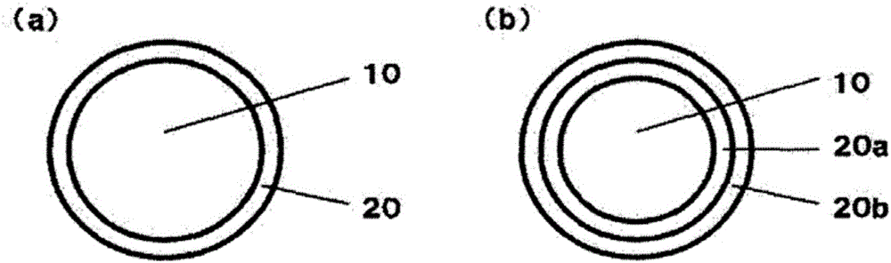
[0186] The obtained resin composition was supplied to a right-angle head 40mm optical cable coating device for resin coating (manufactured by Sei Seisakusho Co., Ltd.), and a coating layer with a thickness of 0.6 mm was coated on the outer circumference of the optical fiber to obtain a diameter of 2.2 mm Optical cable. The above-mentioned test was performed on the obtained optical cable. The evaluation results are shown in Table 2.

Example

[0187] [Examples 2-13, Comparative Examples 1-6]

[0188] Except having changed the composition of the resin composition as shown in Table 1, it carried out similarly to Example 1, and obtained the optical cable. Table 2 shows the evaluation results of the obtained optical cable. It should be noted that the unit of each numerical value in Table 1 is mass %.

[0189] [Table 1]

[0190]

[0191] [Table 2]

[0192]

[0193] The optical cables obtained in Examples 1 to 13 are excellent in flame retardancy, long-term heat resistance, and mechanical properties.

[0194] On the other hand, the optical cables obtained in Comparative Examples 1, 2, 4, and 5 that did not contain the polyolefin resin (B) had poor long-term heat resistance and mechanical properties. In addition, the optical cables obtained in Comparative Examples 3 and 6 that did not contain the chlorinated polyolefin resin (A) had poor flame retardancy and mechanical properties.

[0195] This application claims priority based on...


PUM


Abstract

Provided is an optical fiber cable having excellent flame retardancy, long-term heat resistance and mechanical characteristics. An optical fiber cable according to the present invention comprises an optical fiber and a cladding layer that is provided on the outer circumference of the optical fiber. The cladding layer contains a chlorinated polyolefin resin (A) and a polyolefin resin (B).

Description

technical field [0001] The invention relates to optical cables and sensors. Background technique [0002] Optical fibers are widely used in communication, sensors, lighting, decoration, display and other purposes. Glass-based optical fibers have excellent optical conductivity over a wide wavelength range, but have problems such as poor processability and mechanical properties. On the other hand, the plastic optical fiber includes, for example, an optical fiber having a structure in which a core made of a high-transparency resin such as polymethylmethacrylate is coated with a high-transparency resin having a lower refractive index than the core. made of the periphery. Compared with glass-based optical fibers, plastic optical fibers are characterized by superior processability and flexibility. In addition, with the improvement of manufacturing technology in recent years, the transmission distance of plastic optical fiber has become longer, and its use has gradually become w...

Claims


Application Information

Patent Timeline
IPC IPC(8): G02B6/44C03C25/24D06M15/227D06M101/26
CPCG02B6/4436C03C25/106C03C25/1065C03C25/30G02B6/02033G02B6/443
Inventor 木村刚塚本好宏浅野浩司
Owner MITSUBISHI CHEM CORP
Why Eureka
Try Eureka