
Medical test tube rack

A test tube rack and test tube technology, which is applied in the field of medical appliances, can solve the problems of insufficient clamping force, limited application range, and low efficiency of sampling test tubes, achieve extensive promotional significance and practical value, expand the application range, and break through application restrictions.

Inactive Publication Date: 2016-09-21
QINGDAO BLOOD CENT
View PDF7 Cites 8 Cited by
  • Summary
  • Abstract
  • Description
  • Claims
  • Application Information

AI Technical Summary

Problems solved by technology

[0005] At present, there are several instruments for removing the rubber caps of the test tubes in the market. Some of them need to put the test tubes in a fixed position and uncap the test tubes one by one. The efficiency is low and the degree of automation is not high. It is convenient to uncap the sampling tubes in batches;
[0006] Even if some automatic cap-opening devices have applicable test tube racks, they are mostly custom-made instead of general-purpose test tube racks. The cost is high and the application range is limited, so they can only be used for cap-opening devices; and special custom-made test tube racks, use After a long time, it is easy to be damaged, which will lead to insufficient clamping force on the sampling test tube. When the cover is removed by the cover opening device, the sampling test tube is easily separated from the test tube rack, and then manual auxiliary operation is required, which is likely to cause unnecessary danger. , not only reduces efficiency, but also is particularly inconvenient to operate

Method used


Image

  • Medical test tube rack
  • Medical test tube rack
  • Medical test tube rack

Examples


Embodiment Construction

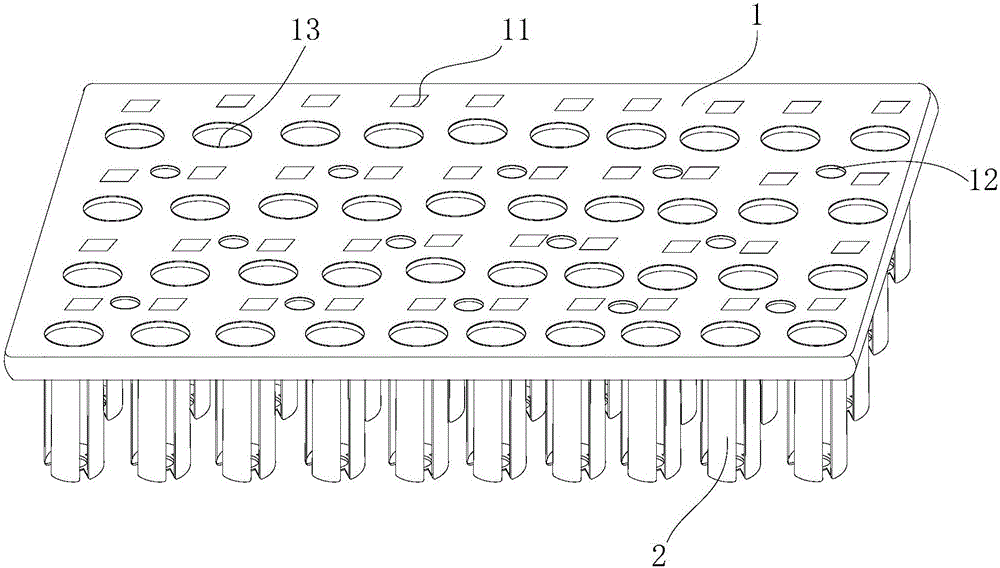
[0029] The present invention provides a medical test tube rack, which can be applied to a cap uncapping machine or equipment to improve the cap uncapping efficiency; it is convenient to use and replace, and the cost is low. The present invention will be further described in conjunction with specific examples below .

[0030] refer to figure 1 , Figure 6 and Figure 7 , the present embodiment proposes a medical test tube rack, including a positioning plate 1, a plurality of positioning tubes 2 vertically arranged on the positioning plate 1 for accommodating test tubes, and a clamping member arranged on the positioning tubes 2 for clamping the test tubes 3. The positioning plate 1 and the nozzle of the positioning tube 2 are located on the same horizontal plane. In this embodiment, the positioning plate 1 is in the shape of a cuboid, with a width of 130mm-160mm, a length of 280mm-350mm, and a thickness of 10mm-15mm. This embodiment is preferred The width value is 150 mm, the...


PUM


Abstract

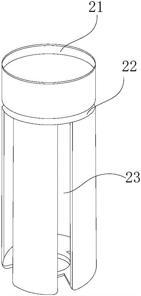
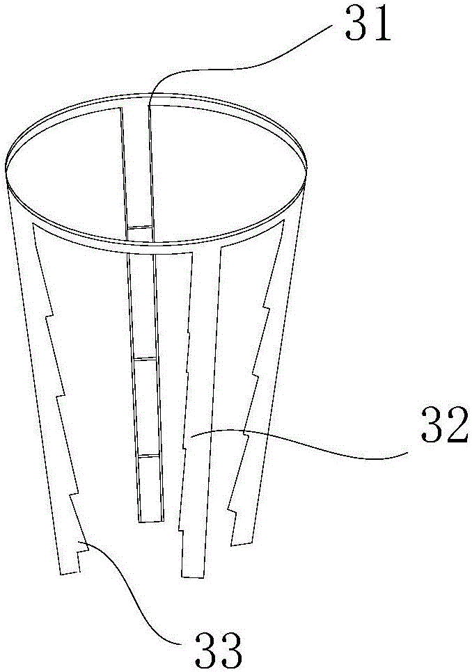
The invention relates to a medical test tube rack which comprises a locating plate, locating pipes and clamping parts. An annular groove is formed in the outer side wall of each locating pipe, and long-strip-shaped strip clamping holes are vertically and symmetrically formed in the portion, below each groove, of the side wall; each clamping part is provided with a circular buckle matched with the corresponding groove, strip clamping buckles which correspond to the strip clamping holes and are used for clamping test tubes are arranged on the circular buckles, the tail ends of the strip clamping buckles are folded inwards and can clamp the test tubes, and the strip clamping buckles are provided with sawtooth-shaped protrusions. According to the medical test tube rack, by means of exquisite design of the locating pipes and the clamping parts, the clamping parts are provided with the strip clamping buckles corresponding to the strip clamping holes of the locating pipes, and the strip clamping buckles are provided with the sawtooth-shaped protrusions; by means of the flexible connection mode of the clamping parts and the locating pipes, clamping force to the test tubes can be guaranteed, the cost is low, replacement of the clamping parts is convenient, the application range is wide, and wide popularization significance is achieved.

Description

technical field [0001] The invention relates to the technical field of medical appliances, in particular to a medical test tube rack. Background technique [0002] As blood bank laboratories gradually apply nucleic acid detection technology to blood screening, the quality of blood samples is crucial for this highly sensitive detection technology. In order not to cause cross-contamination between samples, blood samples are collected by sterile vacuum sampling tubes with rubber caps, and the caps need to be opened before entering the detection and analysis instruments. [0003] At present, there are two ways of manual opening and machine automatic opening. Among them, manual opening and removal not only increases the workload of medical staff, but also poses potential hazards to medical staff, such as laboratory-acquired infections, blood aerosols, scratches, etc. and repetitive strain injuries, etc., so now more machines are used to automatically open the cover. [0004] Wh...

Claims


Application Information

Patent Timeline
Patent Type & Authority Applications(China)
IPC IPC(8): B01L9/06
CPCB01L9/06B01L2200/023B01L2200/12
Inventor 冯秋霞张龙穆侯云高娟娟
Owner QINGDAO BLOOD CENT
Learn More