Tapping machine

A technology for a tapping machine and a machine base, which is applied in the field of tapping machines, can solve the problems of unfavorable processing of workpieces to be processed, increased labor costs, low production efficiency, etc., and achieves the effects of simple structure, high production efficiency, and fast feeding.

Inactive Publication Date: 2016-09-21
PINGHU PINYAO MACHINERY AUTOMATION CO LTD
View PDF8 Cites 5 Cited by
  • Summary
  • Abstract
  • Description
  • Claims
  • Application Information

AI Technical Summary

Problems solved by technology

Further increase the labor cost, making the production efficiency low, which is not conducive to the processing of large quantities of workpieces to be processed

Method used


Image

  • Tapping machine

Examples


Embodiment Construction

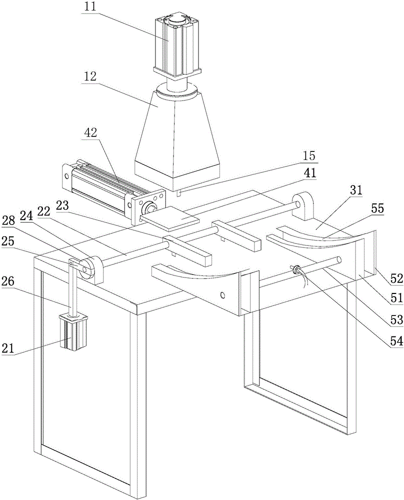
[0014] Such as figure 1 As shown, the tapping machine includes a head assembly, a clamp, a support plate device and a guide rail device, and the head assembly includes a motor 11, a support 12 and a tap 15, and the motor is fixed on the support, The tap is driven by the motor, and the clamp includes a clamp cylinder 21, a first linkage mechanism, a first linkage rod 22, a bead 23 and two first linkage rod seats 24, and the clamp cylinder and the first linkage rod The seats are respectively fixed on the workbench 31, the two ends of the first linkage rod are respectively connected with the two first linkage rod seats through bearings, the bead is fixed on the middle part of the first linkage rod, and the first linkage rod The tail end of a link mechanism is fixed to the end of the first linkage rod, the clamp cylinder drives the first linkage mechanism, and then drives the linkage rod to rotate, thereby clamping or loosening the bead The workpiece to be processed, the support ...


PUM


Abstract

The invention discloses a tapping machine. The tapping machine comprises a machine head assembly, a fixture, a support plate device and a guide rail device; the machine head assembly includes a motor, a base and a screw tap; the motor is fixed on the base; the tap screw is driven by the motor; the fixture includes a fixture cylinder, a first connecting rod mechanism, a first linkage rod, a pressing strip and two first linkage rod seats; the fixture cylinder and the first linkage rod seats are respectively fixed on a workbench; two ends of the first linkage rod are respectively connected with the two first linkage rod seats through bearings; the pressing strip is fixed in the middle part of the first linkage rod; the tail end of the first connecting rod mechanism is fixed to the end part of the first linkage rod; the fixture cylinder drives the first connecting rod mechanism, thereby driving the linkage rod to rotate so as to enable the pressing strip to clamp or loosen a workpiece to be machined; the support plate device includes a support plate and a support plate cylinder; the support plate is fixed on a piston rod of the support plate cylinder; the guide rail device includes two inclined surface guide rail plates and two limiting plates; the two inclined surface guide rail plates are fixed on the workbench; the two limiting plates are respectively located on the outer sides of the two inclined surface guide rail plates; and when the piston rod of the support plate cylinder stretches out, the support plate is joined with the tail ends of the inclined surface guide rail plates, and provide support for the workpiece to be machined.

Description

technical field [0001] The invention relates to a tapping machine. Background technique [0002] The current tapping machine structurally includes a frame, a workbench and a head assembly. The head assembly includes a motor, a feed shaft and a tap. The tap is directly connected to the feed shaft. When in use, when the head assembly goes down When the feed axis is pushed downwards, the tap is driven to move forward stably to tap on the workpiece to be processed; when the head assembly moves upwards, the feed axis is pulled upwards, and finally the tap is driven to withdraw from the workpiece to be processed. The structural tapping machine is only suitable for processing single-form workpieces, and the production efficiency is low. When changing the workpiece to be processed, it is also necessary to change the corresponding fixture to meet the production needs, which increases the cost of production and processing accordingly. [0003] When using the tapping machine for proc...

Claims


Application Information

Patent Timeline
Patent Type & Authority Applications(China)
IPC IPC(8): B23G1/18B23G11/00B23G1/44B23Q3/08
CPCB23G1/18B23G1/44B23G11/00B23G2210/04B23Q3/08B23Q2703/04
Inventor 黄春平
Owner PINGHU PINYAO MACHINERY AUTOMATION CO LTD
Why Eureka
Try Eureka