Tapping travel control mechanism for tapping equipment

A stroke control and equipment technology, which is applied in metal processing equipment, thread cutting machines, manufacturing tools, etc., can solve the problems of large space occupation, inability to use, complicated installation, etc., and achieves convenient installation, commissioning and maintenance, simple design and manufacture, and small occupied space Effect

Active Publication Date: 2016-09-21
BAODING BIAOZHENG MACHINE TOOL
View PDF5 Cites 0 Cited by
  • Summary
  • Abstract
  • Description
  • Claims
  • Application Information

AI Technical Summary

Problems solved by technology

When tapping on a combined machine tool, the tapping stroke control mechanism is generally used on the tapping spindle box. The general tapping stroke control mechanism has a complex structure, high manufacturing cost, and takes up a lot of space. It is required that the position of the worm gear must be installed on the spindle. If there is insufficient space on the left or right side of the spindle box, the installation position of the tapping stroke control mechanism is limited, making it unusable
Moreover, the design and manufacture process of the general-purpose tapping stroke control mechanism is cumbersome, the copper material used in the manufacture of the worm gear is relatively expensive, the processing technology is complicated, and the installation is complicated

Method used


Image

  • Tapping travel control mechanism for tapping equipment
  • Tapping travel control mechanism for tapping equipment

Examples


Embodiment Construction

[0011] The present invention will be further described below in conjunction with the accompanying drawings and specific embodiments.

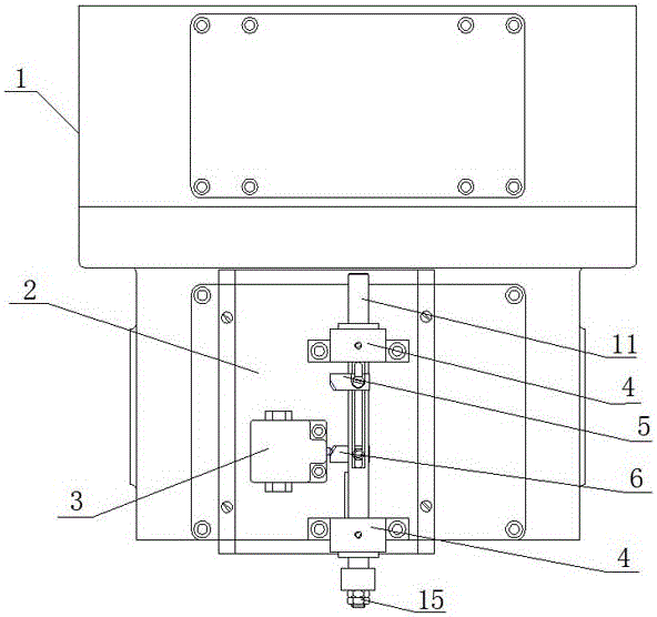
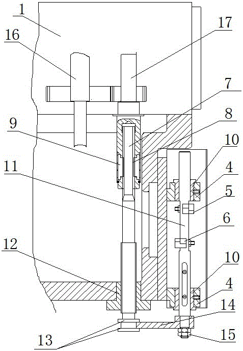
[0012] like figure 1 and figure 2 As shown, this embodiment includes a rod 11 , a cam bar 7 , a cam nut 12 , a connecting plate 14 , a travel switch 3 and a housing 2 . The housing 2 is fixed on one end of the spindle box 1, and one end thereof is connected with a rod 11 that can slide along the guide sleeve 10, and 4 is a guide sleeve bracket. In the spindle box 1, except each main shaft 16, there is also a transmission shaft 17, and the end that the transmission shaft 17 stretches out from the spindle box 1 is hollow. One end of the cam bar 7 is slidably connected in the hollow of the power transmission shaft 17, and its preferred structure is: at least one key 9 is fixed on the hollow inner wall of the power transmission shaft 17, and the relative position of the cam bar 7 is provided with a key corresponding to the key 9. Matching slot ...


PUM


Abstract

The invention discloses a tapping travel control mechanism for tapping equipment. The tapping travel control mechanism comprises a rod, a profiling rod, a profiling nut, a connecting plate, a travel switch and a shell. The shell is fixed to one end of a spindle box. One inner end of the shell is connected with the rod capable of sliding along guide sleeves. Besides spindles, a transmission shaft is further arranged in the spindle box. The end, extending out of the spindle box, of the transmission shaft is hollow. One end of the profiling rod is slidably connected into the hollow part of the transmission shaft. The inner side of the other end of the profiling rod is in threaded connection with the profiling nut. A clamping position is formed by two protrusions on the outer side of the other end of the profiling rod. One end of the connecting plate is fixed to one end of the rod. The other end of the connecting plate is fixedly connected into the clamping position in the end of the profiling rod in a clamped mode. Two stop irons for the travel switch are fixe to the rod, and the distance between the two stop irons is adjustable. The travel switch is fixed to the shell. The tapping travel control mechanism is simple in structure, easy to design and manufacture, low in cost, compact in structure, small in occupied space and convenient to mount, debug and maintain.

Description

technical field [0001] The invention relates to a stroke control mechanism, in particular to a tapping stroke control mechanism used in tapping equipment. Background technique [0002] The combined machine tool is based on serialized and standardized general-purpose components, and is equipped with a small number of special components to cut one or more workpieces according to a predetermined process. On the combined machine tool, multiple The tool processes one or several workpieces, which can reduce material handling and floor space, realize process concentration, improve production efficiency and reduce costs. [0003] Drilling, reaming, reaming, tapping, boring, boring, turning and milling can be completed on the combined machine tool. When tapping on a combined machine tool, the tapping stroke control mechanism is generally used on the tapping spindle box. The general tapping stroke control mechanism has a complex structure, high manufacturing cost, and takes up a lot ...

Claims


Application Information

Patent Timeline
Patent Type & Authority Applications(China)
IPC IPC(8): B23G1/44B23Q5/32B23Q5/52
CPCB23G1/44B23Q5/32B23Q5/52
Inventor 王东旭张奇志
Owner BAODING BIAOZHENG MACHINE TOOL
Why Eureka
Try Eureka