A laser processing device and method for annular microholes

A laser processing method and laser processing technology, which are applied in microstructure devices, manufacturing microstructure devices, laser welding equipment, etc., can solve the problems of single shape, low processing efficiency, uncontrollable micropore size, etc., and achieve simple device and processing. The effect of high efficiency and easy operation

Active Publication Date: 2018-02-27
JIANGSU UNIV
View PDF6 Cites 0 Cited by
  • Summary
  • Abstract
  • Description
  • Claims
  • Application Information

AI Technical Summary

Problems solved by technology

[0005] Aiming at the disadvantages of low processing efficiency, uncontrollable micropore size, and single shape in the laser microhole technology in the prior art, the present invention provides a laser processing device and method for annular microholes, which use precious metal nanoparticles to make laser energy The surface of the workpiece is processed to form a ring-shaped energy-intensified area, which realizes the laser processing of ring-shaped micro-holes, and has the characteristics of high precision, controllable size, high processing efficiency, and simple equipment.

Method used


Image

  • A laser processing device and method for annular microholes
  • A laser processing device and method for annular microholes
  • A laser processing device and method for annular microholes

Examples


Embodiment 1

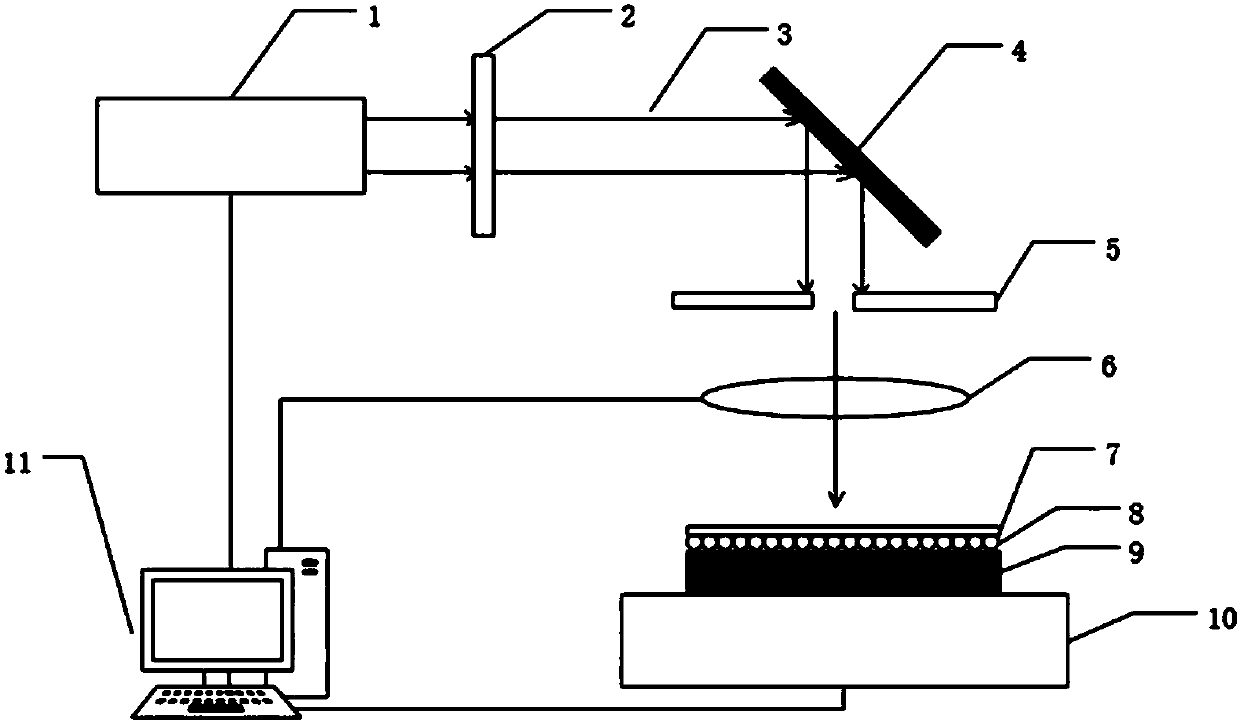
[0040] S1: Build the laser processing device of the annular microhole: adjust the pulse laser 1, the polarization control system 2 and the scanning galvanometer 4 to be in the same optical axis center; adjust the aperture 5, the focusing lens 6, the three-dimensional mobile platform 10 to the scanning galvanometer 4 At the focal point: the pulsed laser 1 , the focusing lens 6 , the three-dimensional mobile platform 10 and the computer control system 11 are electrically connected. Among them, the material of noble metal nanoparticles is gold; the laser used is IPG series pulsed fiber laser, the center wavelength is 1064nm, the repetition frequency is adjustable from 10KHz to 100KHz, the spot diameter is 50μm, and the maximum pulse energy is 1mJ;

[0041] S2: Select workpiece 9, the material is titanium alloy, the size is 20mm*20mm*5mm, and its damage threshold is J 0 =30.5mJ / cm 2 ; Pretreatment of the surface of the workpiece 9: the roughness is sequentially 120, 600, 1200, 30...

Embodiment 2

[0049] It is required to process the inner diameter of the annular microhole d=20nm, at this time p=10, satisfying op Figure 5 , according to the energy enhancement characteristic curve obtained from the solution, the energy enhancement factor A is determined d = 24.5. Turn on the computer control system, know that the spot diameter of the laser beam is 50 μm, calculate and choose the laser energy as 0.019mJ, set the repetition frequency as 50KHz, and the scanning speed as 25m / s. Other processing steps, parameters are the same as in Example 1.

[0050] Observing the processed annular micro-holes with a scanning electron microscope, it was found that the average inner diameter d of the processed annular micro-holes was 18.78nm, which was in good agreement with the processing requirements.


PUM

PropertyMeasurementUnit
diameteraaaaaaaaaa
diameteraaaaaaaaaa

Abstract

The invention provides a laser machining device of an annular micropore. The laser machining device of the annular micropore comprises a pulse laser, a polarization control system, a scanning mirror, an aperture, a focusing lens, a confinement layer, single-layer nano-particles, a three-dimensional moving platform and a computer control system. The pulse laser, the polarization control system and the scanning mirror are distributed along the same optical axis center in order. The aperture and the focusing lens are arranged right below the scanning mirror and the three-dimensional moving platform is arranged right below the focusing lens. The pulse laser, the focusing lens and the three-dimensional moving platform are connected with the computer control system. The creating of the annular micropore is realized in the way of depositing the single-layer nano-particles on the surface of a workpiece by the pretreatment of the surface of the workpiece, then determining the energy strengthening multiple, and machining the surface of the workpiece by the output energy of the pulse laser. According to the device, the laser machining of the annular micropore can be realized. The device has the characteristics of being high in accuracy, controllable in size, high in machining efficiency, simple in equipment and like.

Description

technical field [0001] The invention belongs to the field of laser processing, in particular to a laser processing device and method for annular microholes. Background technique [0002] The advancement of industrial technology has led to the rapid development of laser processing technology, among which laser drilling is the earliest laser processing technology to achieve practicality. Due to the advantages of fast speed, high efficiency and good economic benefits, laser drilling has become one of the main application fields of laser processing. [0003] Laser drilling technology uses a high-power-density laser beam to irradiate the target, so that the temperature of the target surface quickly rises to the vaporization temperature, and evaporation forms holes. A single laser beam can only form one hole. However, when laser drilling technology is applied in the field of micro-nano processing, it faces many problems. The main points are: ① Microholes cannot be made in a larg...

Claims


Application Information

Patent Timeline
Patent Type & Authority Patents(China)
IPC IPC(8): B81C1/00B23K26/382B23K26/082B23K26/0622B23K26/04B23K26/70
CPCB23K26/04B23K26/0622B23K26/082B23K26/382B23K26/702
Inventor 佟艳群石琳任旭东张永康吴笑漪黄建宇王昭周武超
Owner JIANGSU UNIV
Why Eureka
Try Eureka