A fast super-resolution detection device and detection method for optical element defects with random phase shift

A technology for optical components and detection devices, applied in measurement devices, material analysis by optical means, scientific instruments, etc., can solve the problems of limited industrial integration and embeddedness, inconvenient detection of optical components, limited loading frequency, etc. Achieve excellent portability, achieve super-resolution detection, and improve detection efficiency.

Active Publication Date: 2022-03-11
LASER FUSION RES CENT CHINA ACAD OF ENG PHYSICS
View PDF30 Cites 0 Cited by
  • Summary
  • Abstract
  • Description
  • Claims
  • Application Information

AI Technical Summary

Problems solved by technology

[0004] 1. The interferometric structured light illumination super-resolution system based on SLM, in order to avoid the 0th order diffraction effect of SLM, has strict restrictions on the laser beam incident on the SLM (<10°), and most of the optical paths adopt "Z" arrangement, This makes the system bulky and difficult to compress, which greatly limits its industrial integration and embedding
[0005] 2. The SLM-based interferometric structured light illumination super-resolution system, by loading multi-directional and multi-phase phase gratings in the SLM, realizes multi-directional structured lighting modulation on the sample, which is limited by the loading frequency of the SLM (about 100 Hz) , leading to low efficiency of the system in the process of multi-directional, multi-phase modulation and large image acquisition
[0006] 3. Limited by the influence of the laser polarization state, in order to achieve multi-directional, high-contrast structural illumination modulation on the sample, phase gratings in different directions are usually loaded on the SLM in time-sharing, the detection efficiency is low, and it is not convenient for larger apertures. Optical component inspection

Method used


Image

  • A fast super-resolution detection device and detection method for optical element defects with random phase shift
  • A fast super-resolution detection device and detection method for optical element defects with random phase shift

Examples


Embodiment 1

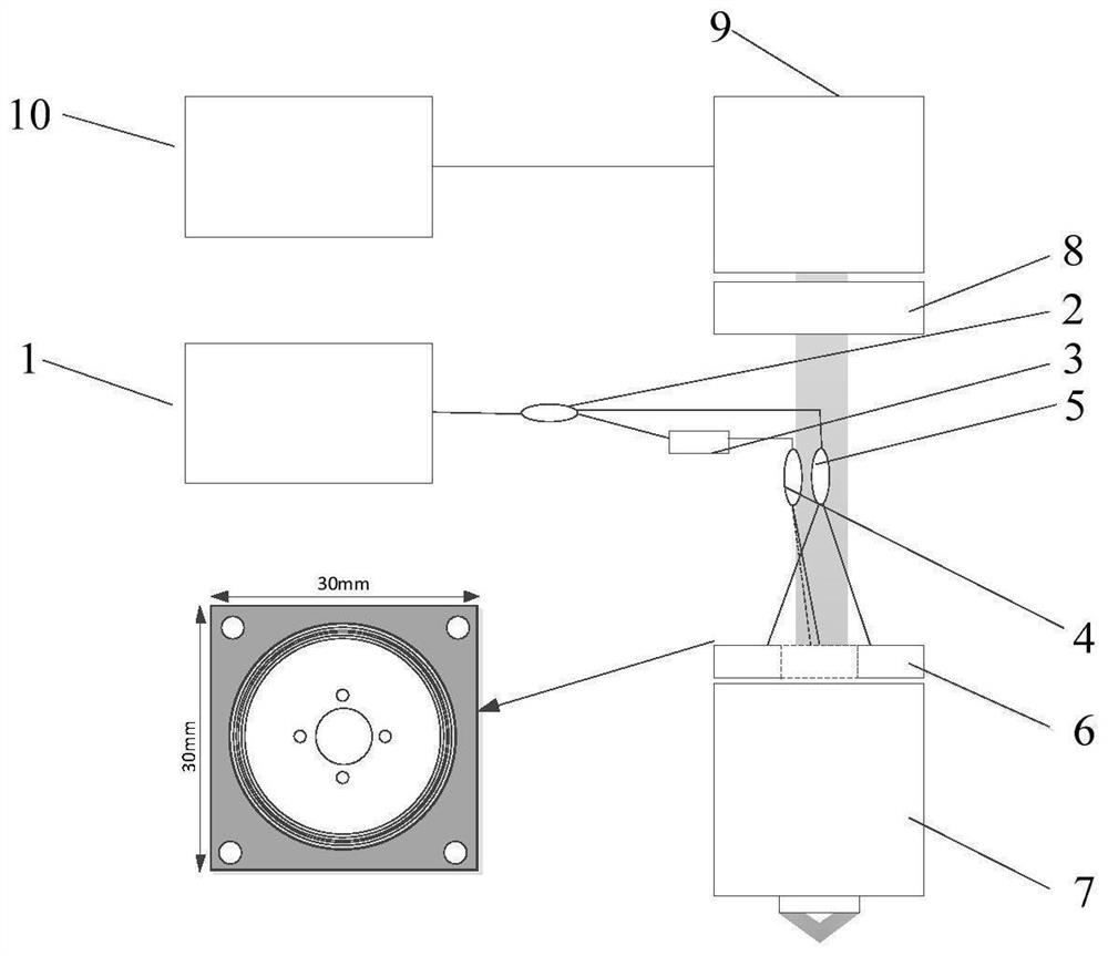
[0033] In order to achieve the goals of miniaturization, portability, high efficiency, random phase shift and low cost, the present invention provides a random phase shift optical element defect fast super-resolution detection device, the adopted technical scheme is as follows: a random phase shift A fast super-resolution detection device for optical component defects, including a laser light source 1, a 1×2 fiber coupler, a microscope objective lens 7, an imaging lens 8, a high-speed camera 9 and a computer 10, and also includes an extruded polarization controller 3, a fiber optic quasi- Straight fixing module 6, the 1×2 fiber coupler includes 1×2 fiber coupler I2, 1×2 fiber coupler II4 and 1×2 fiber coupler III5, and the laser light source 1 passes through the 1×2 fiber coupler Ⅰ2 is equally divided into two beams, one beam is adjusted by the squeeze-type polarization controller 3 to adjust the laser polarization state, and the 1×2 fiber coupler II4 is equally divided into tw...

Embodiment 2

[0040] A detection method of a fast super-resolution detection device for optical element defects with random phase shifting, comprising the following steps:

[0041] Step 1: First place the test sample on the three-dimensional high-precision translation stage of the super-resolution detection device, move the Z-axis of the high-precision translation platform so that the test sample is located at the focal plane of the microscope objective lens 7 of the detection system, and adjust the high-precision translation platform X Axis and Y axis move the starting point of the sample detection area to the imaging field of view of the detection system, and adjust the imaging effect to the best;

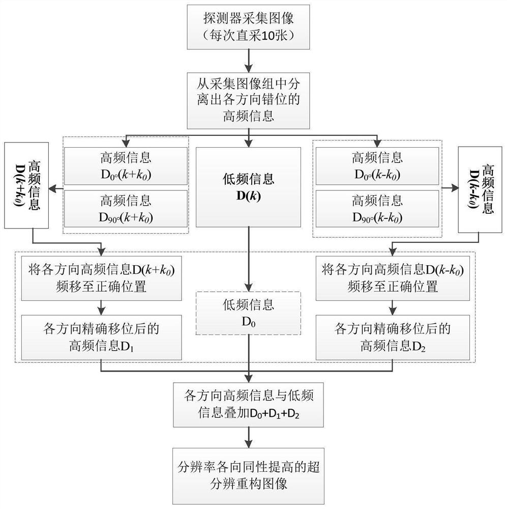
[0042] Step 2: Set the two-dimensional scanning path of the high-precision translation stage, and accurately set the moving rate of the high-precision translation platform according to the acquisition rate of the high-speed camera 9, and complete the acquisition of the same number of original m...


PUM

PropertyMeasurementUnit
diameteraaaaaaaaaa

Abstract

The invention discloses a fast super-resolution detection device and detection method for random phase-shifting optical element defects. The controller adjusts the polarization state of the laser, which is divided into two beams in equal proportions through the 1×2 fiber coupler II, and the other laser output through the 1×2 fiber coupler I passes through the 1×2 fiber coupler III Equally divided into two beams; the four beams of illumination laser light are symmetrically hit on the sample surface through the entrance pupil of the microscope objective lens for interference to form a two-dimensional cosine structured illumination light; the microscope objective lens is used to receive the structured illumination light and modulate it on the sample surface After the reflected and scattered light, the final return imaging signal collection is completed in the high-speed camera through the imaging lens. To achieve the goals of miniaturization, portability, high efficiency, random phase shift and low cost.

Description

technical field [0001] The invention relates to the field of optical element detection, in particular to a random phase-shifting optical element defect fast super-resolution detection device and detection method. Background technique [0002] With the continuous development of ultra-precision machining technology and the application of advanced surface treatment technology, the effective detection and control of micron-scale large-scale defects can now be realized, and the damage threshold of optical components has been greatly improved, but compared with the intrinsic threshold of materials Still about an order of magnitude different. Compared with large-scale defects, micro-nano-scale high-threshold defects are the key factors that limit the further improvement of the damage resistance of optical components. At present, the methods used for surface defect detection of optical components mainly include microscope method, optical scattering method, interference method, lase...

Claims


Application Information

Patent Timeline
Patent Type & Authority Patents(China)
IPC IPC(8): G01N21/958G01N21/01
CPCG01N21/958G01N21/01
Inventor 白金玺张霖石振东马骅许乔柴立群刘丽佳任寰杨一马可
Owner LASER FUSION RES CENT CHINA ACAD OF ENG PHYSICS
Why Eureka
Try Eureka