Articulated crawling robot for steam generator heat pipe detection
A technology of crawling robots and steam generators, applied in manipulators, manufacturing tools, etc., can solve the problems of large overall size of robots, limitation of tube sheet models, small detection area, etc., and achieve easy equipment handling, high safety and stability, The effect of large load
- Summary
- Abstract
- Description
- Claims
- Application Information
AI Technical Summary
Problems solved by technology
Method used
Image
Examples
specific Embodiment approach 1
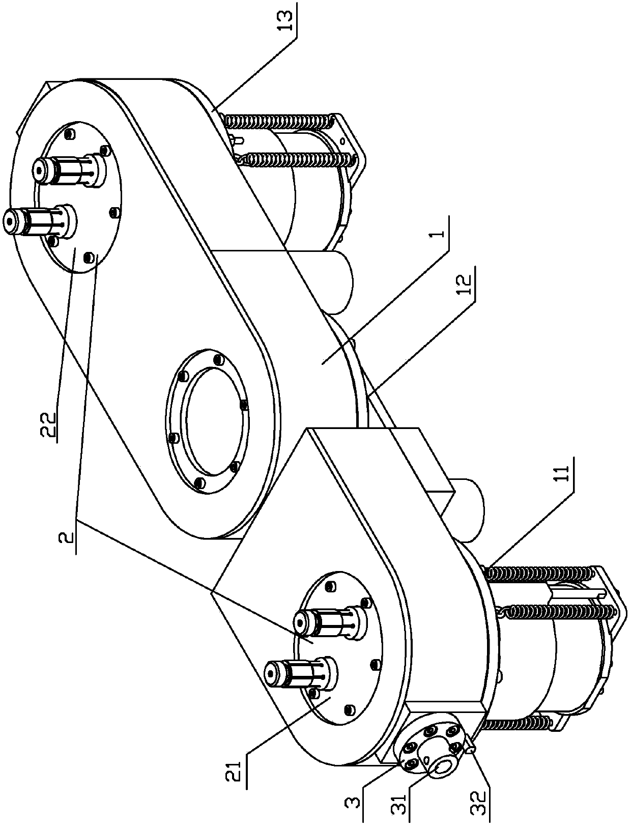
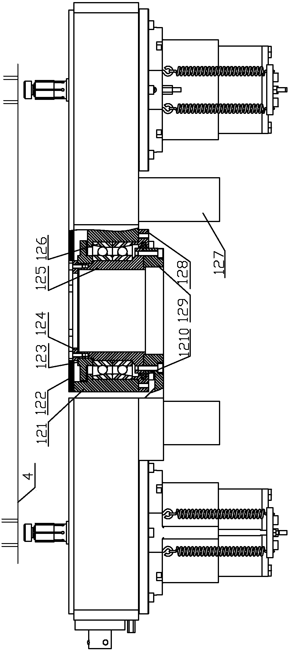
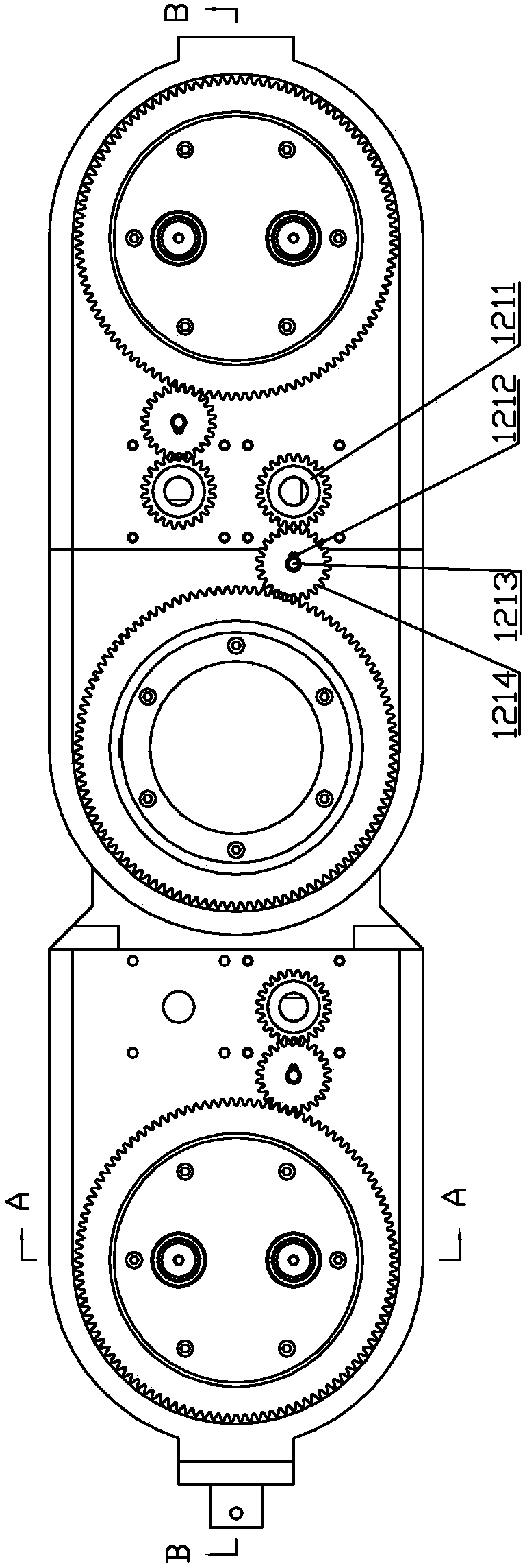
[0028] Specific implementation mode one: combine figure 1 , figure 2 , image 3 , Figure 4 , Figure 5 with Image 6 Describe this embodiment. This embodiment includes a mechanism body 1 and a detection tool interface 3; the mechanism body 1 includes a left rotary joint 11, a middle rotary joint 12, and a right rotary joint 13. The rotary joint 12 and the right rotary joint 13 have the same structure, the left rotary joint 11, the middle rotary joint 12 and the right rotary joint 13 are sequentially connected to form a three-degree-of-freedom mechanical arm, and the toe module 2 includes a left toe assembly 21 and the right toe assembly 22, the left toe assembly 21 is arranged in the left revolving joint 11, the right toe assembly 22 is arranged in the right revolving joint 13, and the detection tool interface 3 is arranged in the left revolving joint 11 On the outer wall or the outer wall of the right rotary joint 13.
specific Embodiment approach 2
[0029] Specific implementation mode two: combination Figure 4 with Figure 5Describe this embodiment. In this embodiment, the left rotary joint 11 includes a joint seat 218, a first main shaft gear 216, a first main shaft 217, a first bearing 219, a first servo motor 2127, a first motor shaft gear 2128, The first connecting shaft 2130 and the first intermediate gear 2131, the first main shaft 217 is set in the joint seat 218, the first main shaft gear 216 is located between the joint seat 218 and the first main shaft 217 and is set on the first main shaft 217 Above, the first bearing 219 is set on the first main shaft 217 and located below the first main shaft gear 216, the first connecting shaft 2130 is installed on one side of the joint seat 218, and the first connecting shaft 2130 is set on the first An intermediate gear 2131 , the first motor shaft gear 2128 is set on the output shaft of the first servo motor 2127 , and the first motor shaft gear 2128 meshes with the fir...
specific Embodiment approach 3
[0030] Specific implementation mode three: combination figure 1 , figure 2 , image 3 , Figure 4 with Figure 5 Describe this embodiment. In this embodiment, the left rotary joint 11 further includes a first baffle plate 215, a first end cover 2112, a first built-in sealing ring 2113, and a first shaft end stop ring 2129. The first main shaft The top of 217 is provided with a first baffle 215, the first end cover 2112 is detachably connected to the bottom of the joint seat 218, the first built-in sealing ring 2113 is set outside the first main shaft 217 and is located in the first end cover 2112, so The first shaft retaining ring 2129 is sleeved on the first connecting shaft 2130 . Other unmentioned structures and connections are the same as those in the second embodiment.
PUM
 Abstract
Description
Claims
Application Information
 - R&D
- Intellectual Property
- Life Sciences
- Materials
- Tech Scout
- Unparalleled Data Quality
- Higher Quality Content
- 60% Fewer Hallucinations
Browse by: Latest US Patents, China's latest patents, Technical Efficacy Thesaurus, Application Domain, Technology Topic, Popular Technical Reports.
© 2025 PatSnap. All rights reserved.Legal|Privacy policy|Modern Slavery Act Transparency Statement|Sitemap|About US| Contact US: help@patsnap.com


