Hydraulic swing cylinder driving joint based robot hydraulic mechanical arm

A hydraulic swing and hydraulic machinery technology, applied in the direction of manipulators, program-controlled manipulators, claw arms, etc., can solve the problems of poor strain capacity, low power density of manipulator arms, and small carrying capacity, so as to reduce the difficulty of manufacturing and facilitate modularization The effect of improving production and carrying capacity

Inactive Publication Date: 2016-09-21
BEIHANG UNIV
View PDF12 Cites 5 Cited by
  • Summary
  • Abstract
  • Description
  • Claims
  • Application Information

AI Technical Summary

Problems solved by technology

Most of the manipulators are single-form applications, and generally only complete specific tasks. In traditional manipulator design applications, the external environment is known. When the demand changes, its ability to change according to the demand is poor
The existing manipulator joint drive generally adopts the method of motor acceleration and deceleration, and usually the power density of this kind of manipulator is relatively low
At the same time, due to the use of motors, the application range of the manipulator is limited in some special environments. For example, the service life of this kind of manipulator will be greatly affected in the nuclear radiation environment.
At the same time, the existing mechanical arm has many problems such as small load capacity and poor rigidity; inflexible movement and low position accuracy; poor versatility, poor strain capacity, and inconvenient maintenance and adjustment.

Method used


Image

  • Hydraulic swing cylinder driving joint based robot hydraulic mechanical arm
  • Hydraulic swing cylinder driving joint based robot hydraulic mechanical arm
  • Hydraulic swing cylinder driving joint based robot hydraulic mechanical arm

Examples


Embodiment 1

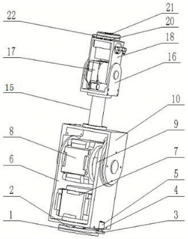
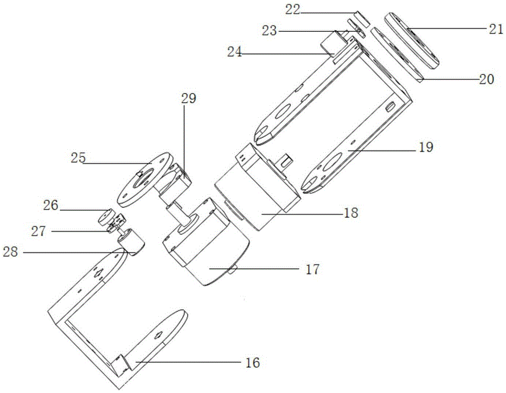
[0034] Such as figure 1 As shown, a robot hydraulic mechanical arm based on a hydraulic swing cylinder driven joint includes a small joint arm and a large joint arm, and the small joint arm and the large joint arm are connected by a joint arm connecting rod 15, and the small joint arm and the large joint arm The drive joints include two hydraulic swing cylinders whose output shaft ends are perpendicular to each other. The hydraulic swing cylinders are arranged in the support frame. The output shaft ends of the hydraulic swing cylinders inside the support frame are connected with gears. The potential of the gears and the potentiometer terminal is gear meshes. In the robot hydraulic mechanical arm based on the hydraulic swing cylinder driving joints of the present invention, the output shaft end of the hydraulic swing cylinder inside the U-shaped support frame of each joint arm is connected with a gear, and is connected with each end of the potentiometer connected by the connect...

Embodiment 2

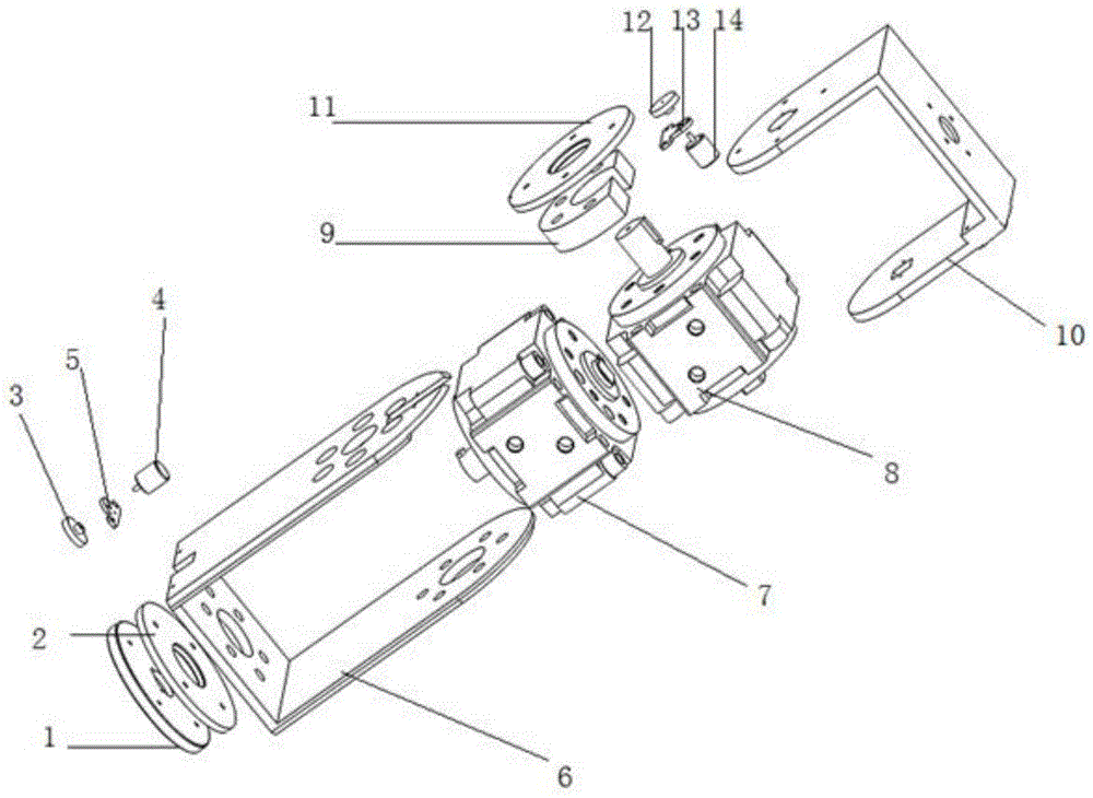
[0056] A robot hydraulic mechanical arm based on hydraulic swing cylinder-driven joints. The difference from Embodiment 1 is that the base connection plate 1 is connected to the large gear A2 through screws to ensure a stable connection with the large gear A2 and to be fixed on the hydraulic swing cylinder together. A7 output shaft.

Embodiment 3

[0058] A robot hydraulic mechanical arm based on a hydraulic swing cylinder-driven joint. The difference from Embodiment 2 is that the output shaft end of the hydraulic swing cylinder A7 passes through the bottom surface of the U-shaped lower support frame 6 of the large joint arm, and its cylinder body is composed of Screws are fixed on the inside of the U-shaped lower support frame 6 of the large joint arm.


PUM


Abstract

The invention relates to a hydraulic swing cylinder driving joint based robot hydraulic mechanical arm. The robot hydraulic mechanical arm includes a small joint arm and a big joint arm; the small joint arm and the big joint arm are connected through a joint arm connection rod; each of driving joints of the small joint arm and the big joint arm includes two hydraulic swing cylinders, wherein output shaft ends of the two hydraulic swing cylinders are mutually perpendicular; the hydraulic swing cylinders are arranged in a support; the output shaft ends of the hydraulic swing cylinders in the support are connected to gears; and the gears are engaged with potentiometer gears at the tails of the potentiometers. The robot hydraulic mechanical arm is simple in structure, is convenient in modular production, and can be applied and promoted to industry; a driving section is driven by the hydraulic swing cylinders, a large output torque can be acquired, and the bearing capability is further improved; and meanwhile, the rigidity is better than that of motor-driven mechanical arms, the production cost is low, the difficulty of manufacture is small, better economy can be acquired, and the practicality is high.

Description

technical field [0001] The invention belongs to the technical field of mechanical design, in particular, the invention relates to a robot hydraulic mechanical arm based on hydraulic swing cylinder-driven joints. Background technique [0002] At present, the mechanical arm is an automatic mechanical device that has been widely used in the field of robotics, and it is widely involved in industrial manufacturing, entertainment services and other fields. Most of the manipulators are used in a single form, and generally only complete specific tasks. In traditional manipulator design applications, the external environment is known. When the demand changes, its ability to change according to the demand is poor. Existing manipulator joints are generally driven by electric motor acceleration and deceleration machines, and the power density of such manipulators is usually relatively low. At the same time, due to the use of motors, the scope of use of the manipulator is limited in som...

Claims


Application Information

Patent Timeline
Patent Type & Authority Applications(China)
IPC IPC(8): B25J18/00B25J9/14
Inventor 陶永胡磊孙贝高彭彭刘辉
Owner BEIHANG UNIV
Why Eureka
Try Eureka