

Film blowing and printing integrated machine
An integrated machine and printing machine technology, applied in the field of film blowing and printing integrated machine, can solve the problems of waste, poor film quality, complicated processes, etc., and achieve the effect of convenient and simple operation.
- Summary
- Abstract
- Description
- Claims
- Application Information
AI Technical Summary
Problems solved by technology
Method used
Image

Examples
Embodiment 1
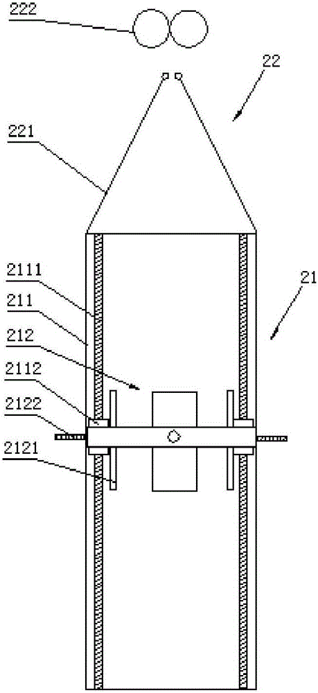
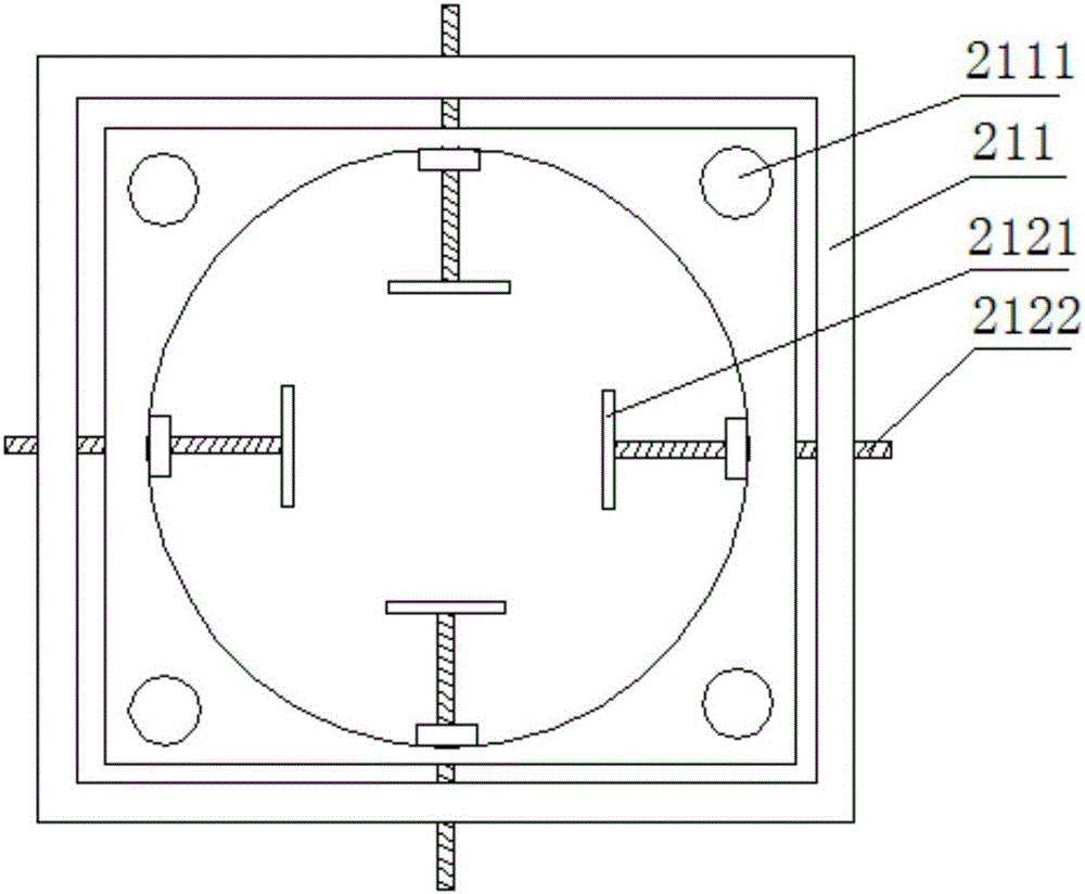
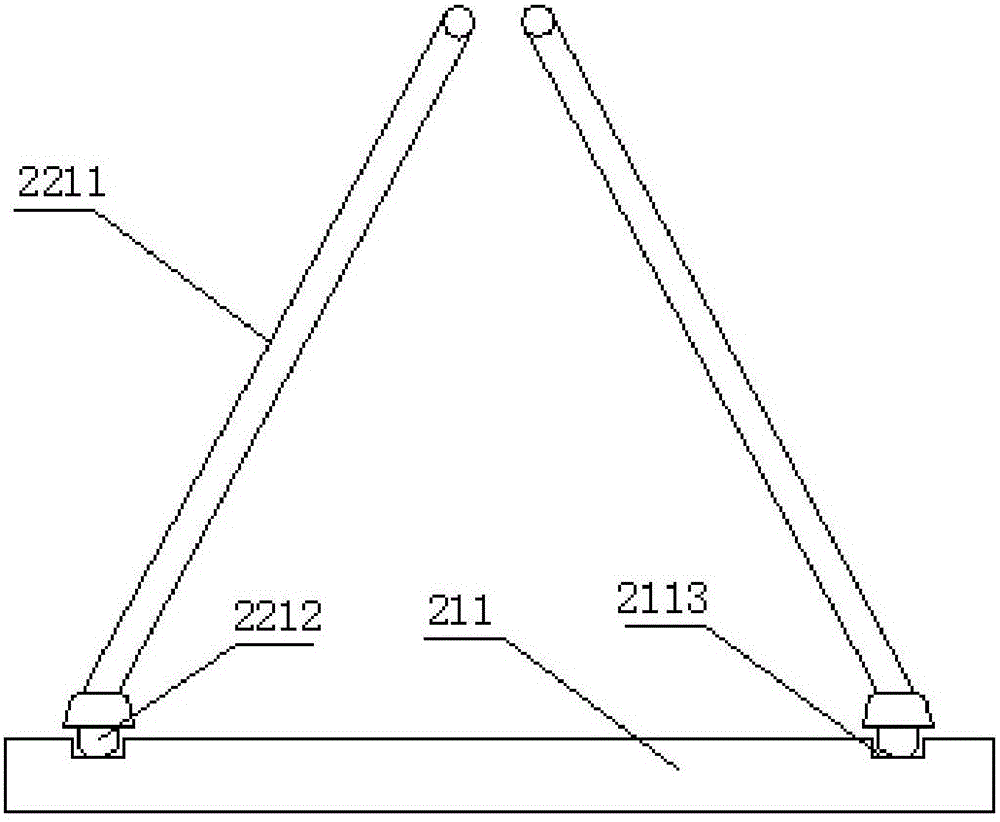
[0042] Such as figure 1 , 2 , As shown in 3, the traditional bubble stabilization rack does not have the adjustment of height and diameter, and its adaptability is poor. The bubble stabilizing rack 21 provided by the present invention includes a bracket 211; a bubble stabilizing frame 212 is fixed on the inner wall of the bracket 211; a guide column 2111 is arranged on the bracket 211; the bubble stabilizing frame 212 moves up and down along the guide column 2111.
[0043] The bracket 211 provided by the present invention is a rectangular section bracket 211 composed of 4 uprights; a guide post 2111 is respectively fixed on the 4 uprights; the four corners of the foam stabilizing frame 212 have sliding holes; the foam stabilizing frame 212 is sleeved on the Move up and down on the guide post 2111. In order to facilitate the vertical movement and fixing of the bubble stabilizing frame 212, the guide post 2111 provided by the present invention is a screw; the position between ...
Embodiment 2
[0049] Such as Figure 4 , Figure 5 As shown, the tension roller set includes a plurality of tension rollers 32; the plurality of tension rollers 32 are all fixed on the frame parallel to each other. All be provided with antistatic device 31 on each tension roller 32; Antistatic device 31 is to be provided with a wet cloth strip along the axial direction of tension roller 32; Pass between the rollers 32;
Embodiment 3
[0051] Such as Image 6 , Figure 7 As shown, the printing assembly includes a version roller 41, a rubber roller 42, and a scraper 43; , and the scraper 43 is inclined downward from the contact end with the version roller 41 towards the other end; the printing assembly also includes an ink absorbing device; the ink absorbing device includes a suction pipe 44; the mouth of the suction pipe 44 is flat; the lower edge of the mouth of the suction pipe 44 is attached to the scraper Plate 43 and is in printing position of version roller 41.
[0052] The printing assembly also includes a primary drying device; the primary drying device has an air supply port 45; the air supply port 45 is above the scraper 43 and blows air to the film printing position; the wind direction of the primary drying device is from the air outlet to the direction of the film. The direction is sloping from bottom to top.
[0053] The printing machine also includes a second drying device 46; the second dry...
PUM
 Abstract
Description
Claims
Application Information