

Gas-carbon co-production device
A gas-charcoal and reaction device technology, applied in the gasification process, the manufacture of combustible gas, the petroleum industry, etc., can solve problems such as low work efficiency, and achieve the effect of improving efficiency, preventing accumulation, and preventing stuck or stuck.
Inactive Publication Date: 2016-09-21
FUJIAN MINAN MACHINERY MFG
View PDF2 Cites 3 Cited by
- Summary
- Abstract
- Description
- Claims
- Application Information
AI Technical Summary
Problems solved by technology
Moreover, after the charcoal is burned, it often needs to be manually cleaned and discharged, and the work efficiency is low.
Method used
View moreImage
Smart ImageViewing Examples

Examples
Embodiment Construction
[0017] The present invention will be further described in conjunction with the accompanying drawings and specific embodiments.
Login to View More PUM
 Abstract
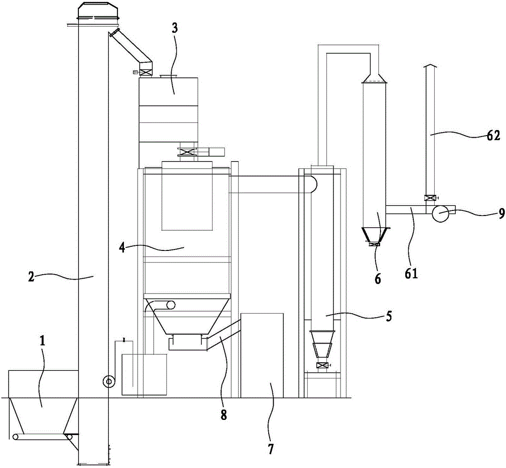
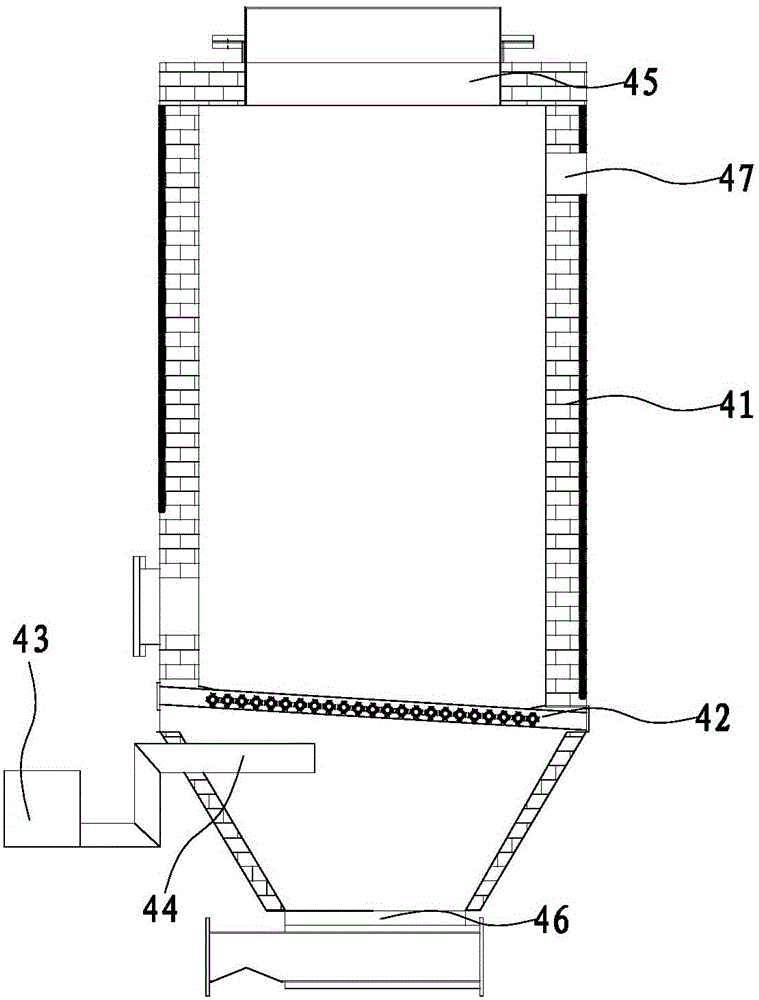
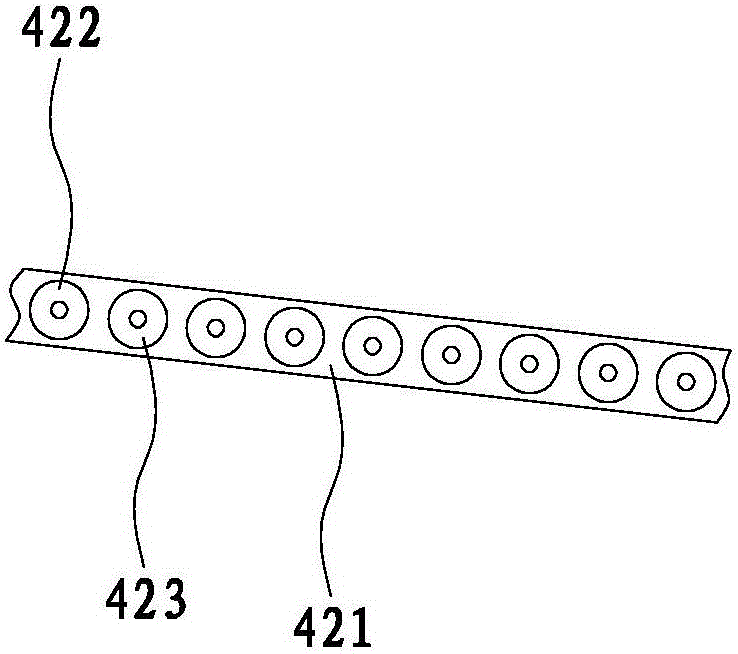
The invention relates to a gas-carbon co-production device, comprising a rack, and a hopper, a reaction device, a gas purifying device used for purifying gas output by the reaction device and a gas water treatment device used for removing water contained in the gas which are arranged on the rack according to a production line, wherein the reaction device comprises a furnace body, a fire grate arranged in the furnace body, an air blower arranged outside the furnace body, and a blower tube which is arranged under the fire grate and is communicated with the air blower; a feeding hole communicated with the hopper is formed in the upper end of the furnace body, and a slag hole is formed in the lower end of the furnace body; a gas outlet communicated with the gas purifying device is formed in the furnace body; the rack is provided with a crusher; a spiral conveyor used for conveying carbon residue discharged by the furnace body into the crusher is arranged on the rack and between the crusher and the slag hole; the gas water treatment device is connected with a gas conveying pipeline.
Description
technical field [0001] The invention relates to a gas-carbon cogeneration device. Background technique [0002] At present, the gas produced by the existing gas-carbon cogeneration equipment often has a lot of dust particles and oil particles when it is output, resulting in a lower combustion rate, and more combustion impurities, which may even lead to incombustibility. Moreover, after the wood is damp and burned, a large amount of water vapor will be produced, so the output gas will contain water vapor, which also leads to a low combustion rate. How to remove dust particles, oil particles, and water vapor has become the key. Moreover, after the charcoal is burned, it often needs to be manually cleaned and discharged, and the work efficiency is low. Contents of the invention [0003] Therefore, in view of the above problems, the present invention proposes a gas-carbon cogeneration device with clean output gas, low gas moisture content, and automatic charcoal discharge an...
Claims
Login to View More Application Information
Patent Timeline
 Patent Type & AuthorityApplications(China)
IPC IPC(8): C10J3/00C10J3/84C10J3/72
CPCC10J3/00C10J3/72C10J3/84C10J2300/0906C10J2300/1603
Inventor刘阿小戴海珊吴联平戴琪琳张公敏傅德丙
OwnerFUJIAN MINAN MACHINERY MFG