
Magnetron Sputtering Device

A technology of magnetron sputtering device and monitoring device, which is applied in the direction of sputtering coating, vacuum evaporation coating, coating, etc., which can solve the problems of increased uncertainty, difficulty in adjusting the magnetic target distance, and the inability to monitor the consumption of target materials and other issues to achieve the effect of ensuring uniformity and stability and improving quality

Active Publication Date: 2018-10-12
CHENGDU VISTAR OPTEOLECTRONICS CO LTD
View PDF2 Cites 0 Cited by
  • Summary
  • Abstract
  • Description
  • Claims
  • Application Information

AI Technical Summary

Problems solved by technology

[0003] The magnetron sputtering device coats the substrate through the target material, and the target material is continuously consumed as it is used. Since the target material is located in the cavity of the magnetron sputtering device, it is impossible to monitor the actual consumption of each part of the target material. , so that the distance between the magnet and the target (referred to as the magnetic target distance) cannot be adjusted accordingly
At present, the DC four-point probe measurement method (Rs method) is usually used to measure the uniformity of the film layer resistance to judge the degree of target consumption, and then artificially determine whether the magnetic target distance needs to be adjusted and the specific adjustment situation. The participation of factors will inevitably increase the uncertainty, which will cause certain difficulties in the adjustment of the magnetic target distance.

Method used


Image

  • Magnetron Sputtering Device
  • Magnetron Sputtering Device
  • Magnetron Sputtering Device

Examples


Embodiment Construction

[0017] In order to further explain the technical means and effects adopted by the present invention to achieve the intended invention purpose, the specific implementation, structure, features and effects of the present invention will be described in detail below in conjunction with the accompanying drawings and preferred embodiments.

[0018] The orientations "upper" and "lower" mentioned in the description of the present invention are only used to indicate the relative orientation relationship, and refer to the positional relationship embodied in the drawings of the specification.

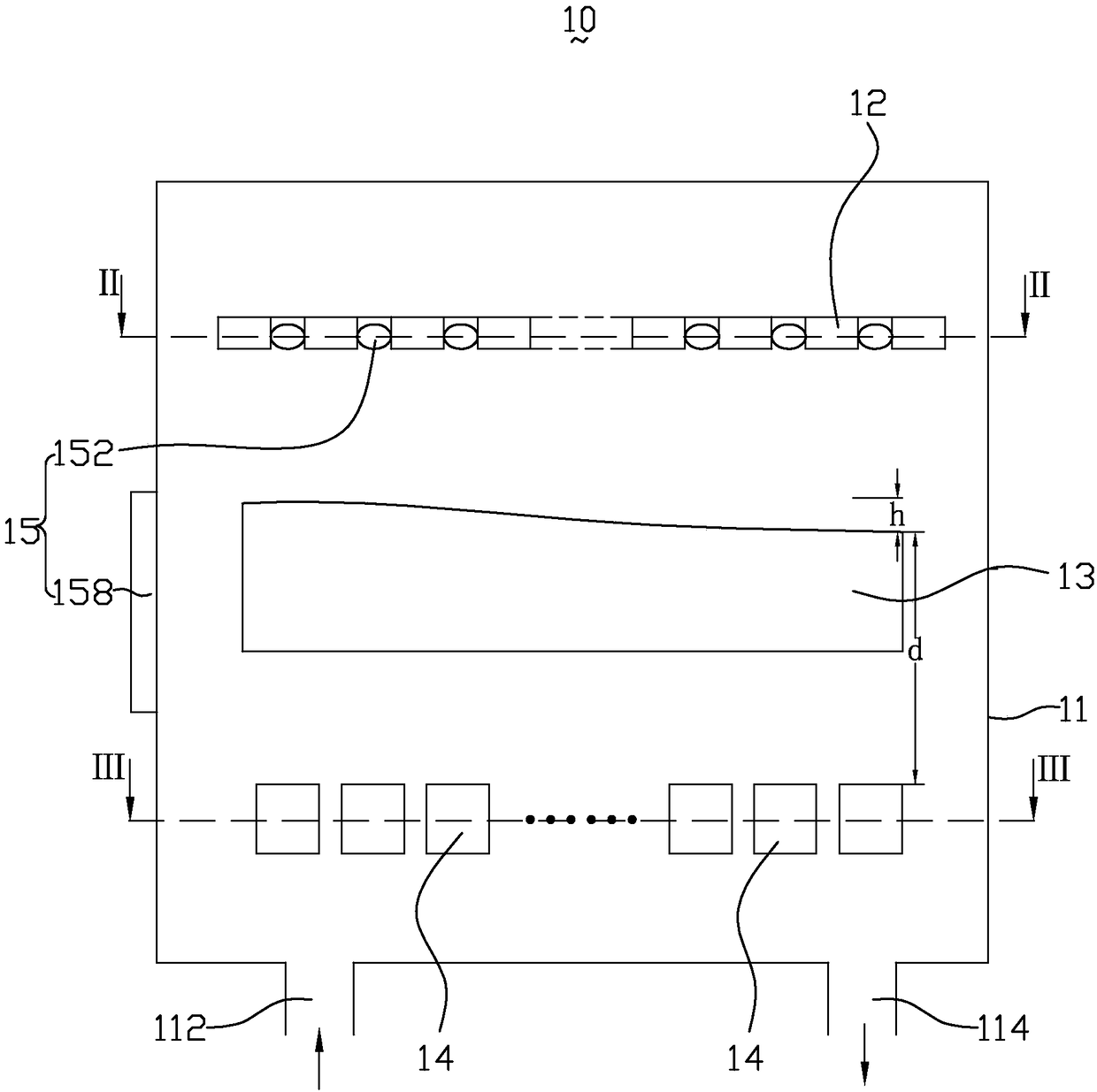
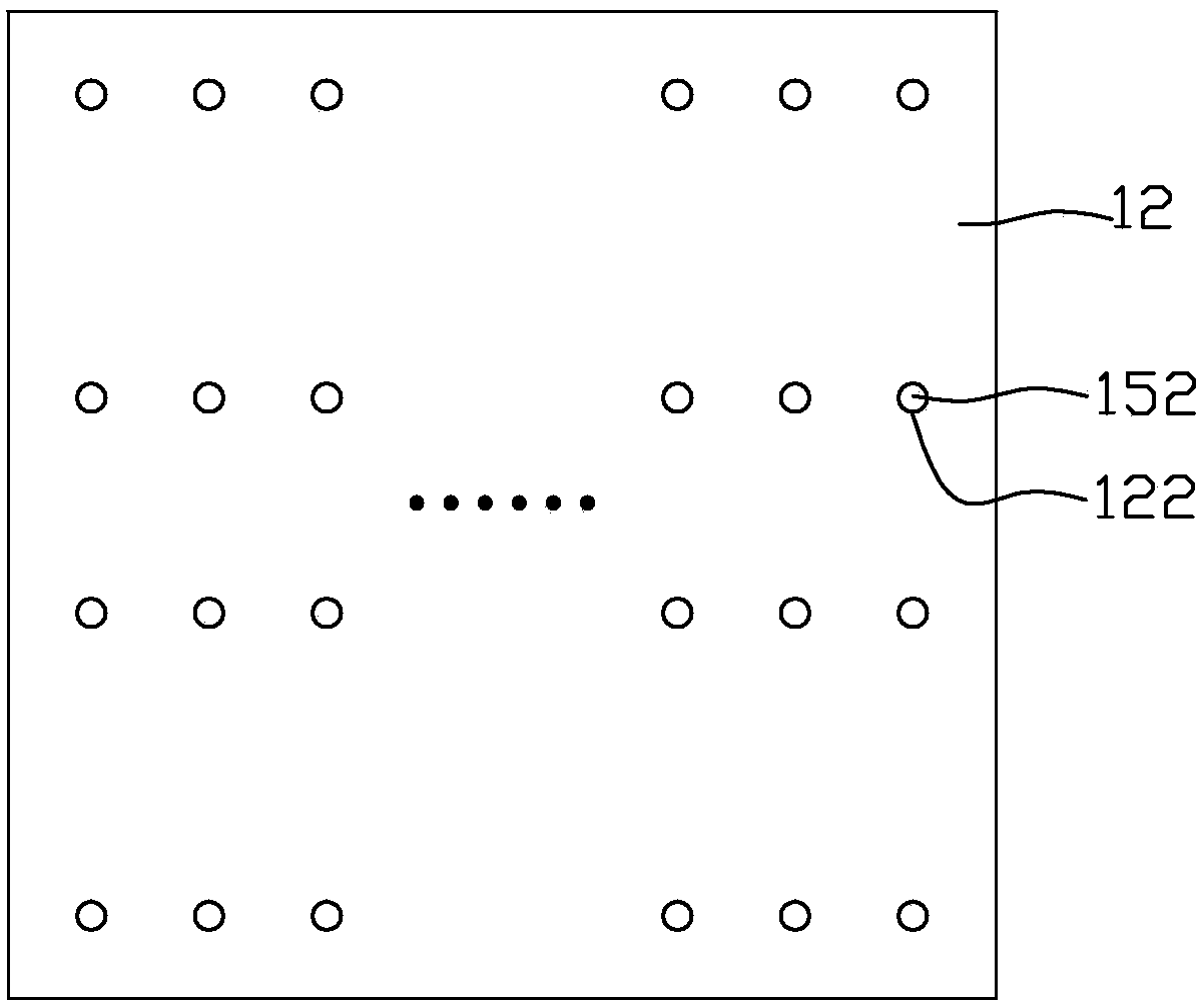
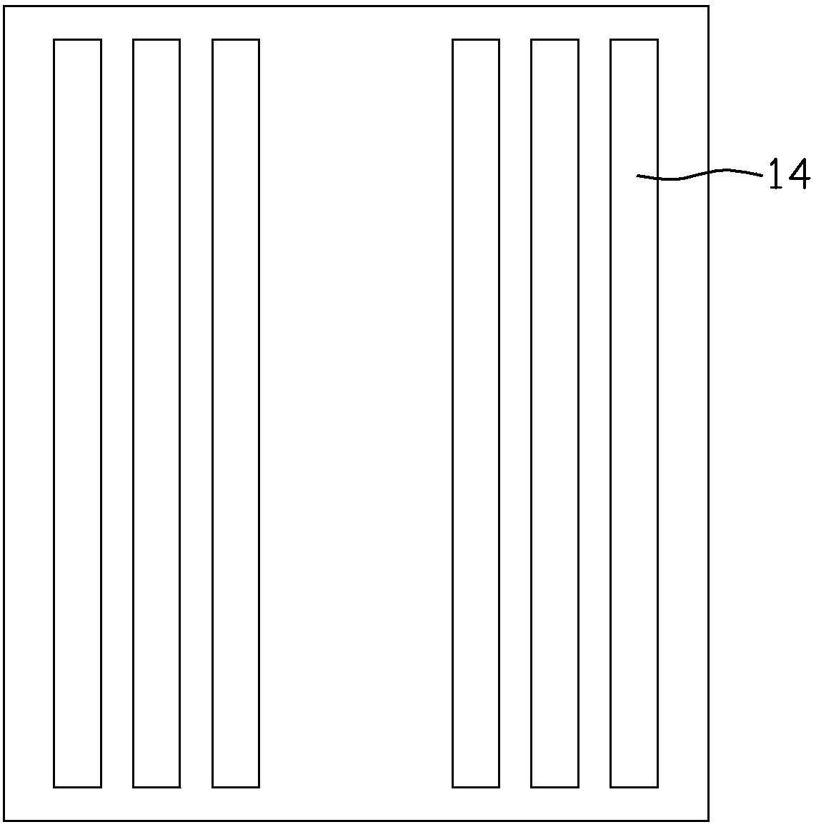
[0019] figure 1 is a schematic structural view of the magnetron sputtering device of the present invention, figure 2 yes figure 1 The cross-sectional view at II-II, image 3 yes figure 1 For the cross-sectional view at III-III, please refer to Figure 1 to Figure 3 As shown, the magnetron sputtering device 10 includes a working chamber 11 , a substrate 12 , a target 13 , a magnet 14 , and a t...


PUM


Abstract

A magnetron sputtering device comprises a work cavity, a base, a target material and magnets; the base, the target material and the magnets are sequentially arranged in the work cavity from top to bottom; and the multiple magnets are each in a shape of a strip and are horizontally arranged in parallel at intervals. The magnetron sputtering device further comprises a target material consumption monitoring device which comprises laser transceiving devices, a computing module and a magnet adjusting module; the multiple laser transceiving devices are evenly arranged on the base and electrically connected with the computing module; the laser transceiving devices record the laser receiving and transmitting time difference, and the target material consumption amount of a position corresponding to each laser transceiving device is worked out through the computing module; and the magnet adjusting module is electrically connected with the computing module and sequentially adjusts the corresponding magnetic target distance of each laser transceiving device according to the computing result of the computing module. The magnetron sputtering device can accurately monitor the target material consumption amount in real time, accurately adjust the magnetic target distance, improve the sputter coating quality and guarantee the coating uniformity and stability.

Description

technical field [0001] The invention relates to the technical field of vacuum coating, in particular to a magnetron sputtering device. Background technique [0002] Magnetron sputtering technology has developed into one of the very important technologies in industrial coating. Because of its advantages of high sputtering rate, high deposition rate, low deposition temperature, and good film quality, it has attracted more and more attention from relevant parties. For example, magnetron sputtering technology has been applied to many production and scientific research fields, and has been widely used in many aspects such as electronics, optics, surface functional films, and thin film luminescent materials. In particular, transparent conductive glass prepared by magnetron sputtering technology is currently widely used in flat panel displays, solar cells, architectural glass, microwave and radio frequency shielding devices and devices, sensors and other fields. [0003] The magn...

Claims


Application Information

Patent Timeline
Patent Type & Authority Patents(China)
IPC IPC(8): C23C14/35C23C14/54H01J37/34
CPCC23C14/35C23C14/54H01J37/3405H01J37/3479
Inventor 张杨杨大可乔恩琳吉冠腾
Owner CHENGDU VISTAR OPTEOLECTRONICS CO LTD
Learn More